2.6.5 Sample: Use ENU to Create the Second Machine Panel
After organizing the function key and signal lights of the second machine panel, the second machine panel use ENU to connect with the CNC controller and assume the ENU setting as the first I/O unit.
Step 1
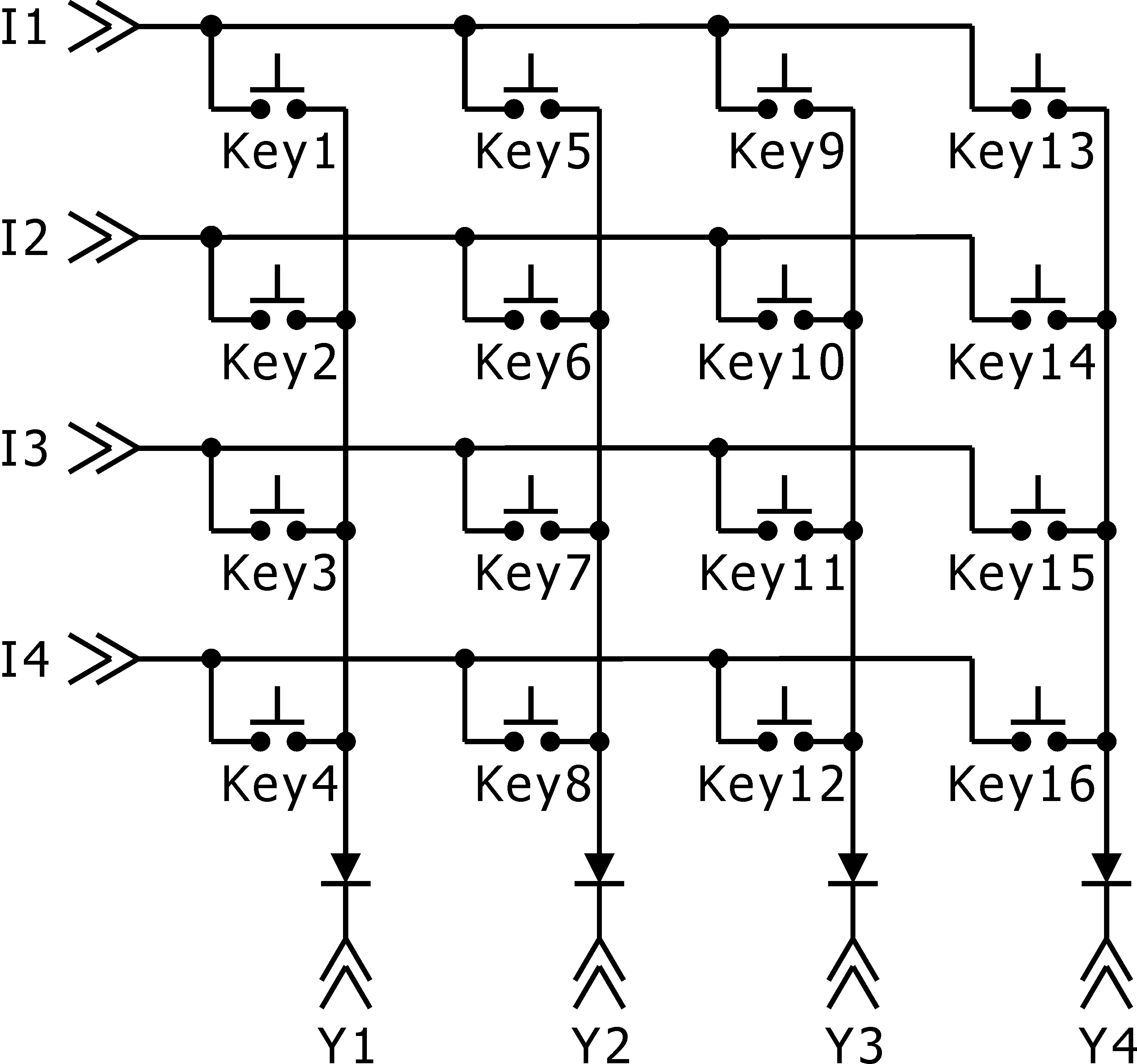
Create the key scanning electric circuit drawing.

Key Scanning Electric Circuit Drawing
Step 2
Declare each key.
int key1,key2,key3,key4,key5,key6,key7,key8,
key9,key10,key11,key12,key13,key14,key15,key16;
Within the PLC define the data line (I1, I2, I3, I4).
Data line |
PLC definition |
Explain |
I1 |
plc.gdi[0].bit.bit00 |
ENU P0 first pin |
I2 |
plc.gdi[0].bit.bit01 |
ENU P0 second pin |
I3 |
plc.gdi[0].bit.bit02 |
ENU P0 third pin |
I4 |
plc.gdi[0].bit.bit03 |
ENU P0 fourth pin |
At PLC definition scan line (Y1, Y2, Y3, Y4).
Scan line |
PLC definition |
Explain |
Y1 |
plc.gdo[0].bit.bit00 |
ENU P2 first pin |
Y2 |
plc.gdo[0].bit.bit01 |
ENU P2 second pin |
Y3 |
plc.gdo[0].bit.bit02 |
ENU P2 third pin |
Y4 |
plc.gdo[0].bit.bit03 |
ENU P2 fourth pin |
The function of each key within PLC.
Key definition |
Key |
Explain |
#define KEY_CycleStart |
key1 |
Program execute |
#define KEY_FeedHold |
key2 |
Program pause |
#define KEY_Home |
key3 |
Home mode |
#define KEY_AutoHome |
key4 |
Auto return to zero |
#define KEY_Jog |
key5 |
JOG mode |
#define KEY_HDL |
key6 |
Handwheel mode |
#define KEY_SP_CW |
key7 |
Spindle clockwise spin |
#define KEY_SP_CCW |
key8 |
Spindle counterclockwise spin |
#define KEY_X_Jog_P |
key9 |
X-axis positive JOG movement button |
#define KEY_X_Jog_N |
key10 |
X-axis negative JOG movement button |
#define KEY_Y_Jog_P |
key11 |
Y-axis positive JOG movement button |
#define KEY_Y_Jog_N |
key12 |
Y-axis negative JOG movement button |
#define KEY_Z_Jog_P |
key13 |
Z-axis positive JOG movement button |
#define KEY_Z_Jog_N |
key14 |
Z-axis negative JOG movement button |
#define KEY_A_Jog_P |
key15 |
A-axis positive JOG movement button |
#define KEY_A_Jog_N |
key16 |
A-axis negative JOG movement button |
Step 3
Inside PLC Run to write the program of the scanning input button.
switch(secondPanelKeyScan){
case 0:
Y1 = 1;
Y2 = 0;
Y3 = 0;
Y4 = 0;
secondPanelKeyScan ++;
break;
case 1:
key1 = I1;
key2 = I2;
key3 = I3;
key4 = I4;
Y1 = 0;
Y2 = 1;
Y3 = 0;
Y4 = 0;
secondPanelKeyScan ++;
break;
case 2:
key5 = I1;
key6 = I2;
key7 = I3;
key8 = I4;
Y1 = 0;
Y2 = 0;
Y3 = 1;
Y4 = 0;
secondPanelKeyScan ++;
break;
case 3:
key9 = I1;
key10 = I2;
key11 = I3;
key12 = I4;
Y1 = 0;
Y2 = 0;
Y3 = 0;
Y4= 1;
secondPanelKeyScan ++;
break;
case 4:
key13 = I1;
key14 = I2;
key15 = I3;
key16 = I4;
Y1 = 1;
Y2 = 0;
Y3 = 0;
Y4 = 0;
secondPanelKeyScan = 1;
break;
}
Step 4
Within PLC Run define the corresponding function of each button, for example: KEY_CycleStart corresponds to PLC output plc.vto0.bit.clsrt, as a start signal to notify NC program.
void PLCAPI plcRun(Status & sts, PlcBlock & plc){
……………………………;
plc.vto0.bit.clsrt=KEY_CycleStart;
plc.vto0.bit.fhold=KEY_FeedHold;
……………………………;
}
Step 5
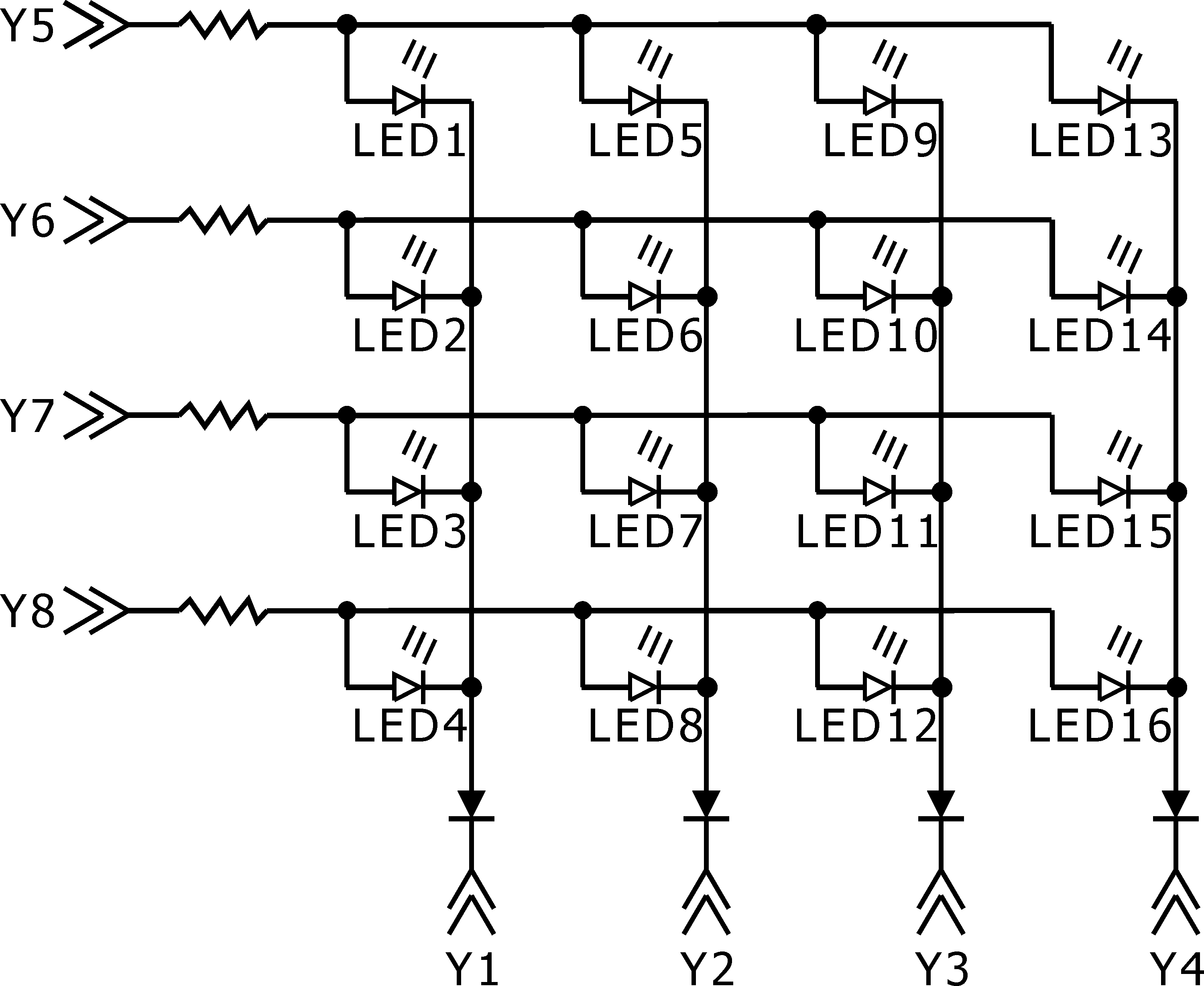
Draw button LED light output scanning electric circuit drawing.

LED Light Output Scanning Electric Circuit Drawing
Step 6
Declare each key.
int LED1,LED2,LED3,LED4,LED5,LED6,LED7,LED8,
LED9,LED10,LED11,LED12,LED13,LED14,LED15,LED16;
Within PLC define the definition of data line (Y5, Y6, Y7, Y8).
Data line |
PLC definition |
Explain |
Y5 |
plc.gdo[0].bit.bit04 |
ENU P2 fifth pin |
Y6 |
plc.gdo[0].bit.bit05 |
ENU P2 sixth pin |
Y7 |
plc.gdo[0].bit.bit06 |
ENU P2 seventh pin |
Y8 |
plc.gdo[0].bit.bit07 |
ENU P2 eighth pin |
Within PLC define scan line (Y1, Y2, Y3, Y4).
Scan line |
PLC definition |
Explain |
Y1 |
plc.gdo[0].bit.bit00 |
ENU P2 first pin |
Y2 |
plc.gdo[0].bit.bit01 |
ENU P2 second pin |
Y3 |
plc.gdo[0].bit.bit02 |
ENU P2 third pin |
Y4 |
plc.gdo[0].bit.bit03 |
ENU P2 fourth pin |
Within PLC define the function of each LED button.
LED definition |
LED |
Explain |
#define LED_CycleStart |
LED1 |
Program execution signal light |
#define LED_FeedHold |
LED2 |
Program pause signal light |
#define LED_Home |
LED3 |
Return to zero module signal light |
#define LED_AutoHome |
LED4 |
Automatically return to zero signal light |
#define LED_Jog |
LED5 |
JOG mode signal light |
#define LED_HDL |
LED6 |
Handwheel mode signal light |
#define LED_SP_CW |
LED7 |
Spindle positive spion signal light |
#define LED_SP_CCW |
LED8 |
Spindle negative spin signal light |
#define LED_X_Jog_P |
LED9 |
X-axis positive JOG signal light |
#define LED_X_Jog_N |
LED10 |
X-axis negative JOG signal light |
#define LED_Y_Jog_P |
LED11 |
Y-axis positive JOG signal light |
#define LED_Y_Jog_N |
LED12 |
Y-axis negative JOG signal light |
#define LED_Z_Jog_P |
LED13 |
Z-axis positive JOG signal light |
#define LED_Z_Jog_N |
LED14 |
Z-axis negative JOG signal light |
#define LED_A_Jog_P |
LED15 |
A-axis positive JOG signal light |
#define LED_A_Jog_N |
LED16 |
A-axis negative JOG signal light |
Step 7
With PLC Run of scan input key of program adds the program of scan LED key, the state of LED1~LED16 is executed by other parts of PLC Run.
switch(secondPanelKeyScan){
case 0:
Y1 = 1;
Y2 = 0;
Y3 = 0;
Y4 = 0;
Y5 = !LED1;
Y6 = !LED2;
Y7 = !LED3;
Y8 = !LED4;
secondPanelKeyScan ++;
break;
case 1:
key1 = I1;
key2 = I2;
key3 = I3;
key4 = I4;
Y1 = 0;
Y2 = 1;
Y3 = 0;
Y4 = 0;
Y5 = !LED5;
Y6 = !LED6;
Y7 = !LED7;
Y8 = !LED8;
secondPanelKeyScan ++;
break;
case 2:
key5 = I1;
key6 = I2;
key7 = I3;
key8 = I4;
Y1 = 0;
Y2 = 0;
Y3 = 1;
Y4 = 0;
Y5 = !LED9;
Y6 = !LED10;
Y7 = !LED11;
Y8 = !LED12;
secondPanelKeyScan ++;
break;
case 3:
key9 = I1;
key10 = I2;
key11 = I3;
key12 = I4;
Y1 = 0;
Y2 = 0;
Y3 = 0;
Y4 = 1;
Y5 = !LED13;
Y6 = !LED14;
Y7 = !LED15;
Y8 = !LED16;
secondPanelKeyScan ++;
break;
case 4:
key13 = I1;
key14 = I2;
key15 = I3;
key16 = I4;
Y1 = 1;
Y2 = 0;
Y3 = 0;
Y4 = 0;
Y5 = !LED1;
Y6 = !LED2;
Y7 = !LED3;
Y8 = !LED4;
secondPanelKeyScan = 1;
break;
}
Please be aware: Because the output of the light signal is via PLC fast scanning. Cycle of PLC scanning is 4 ms, so when LED number increase, it will cause the lights on the interface to sparkle and ENU output pin power flow is 10 mA, if you want to improve the problem of not having enough power while the signal lights are sparkling and the problem of the driver not having enough power, must place another IC upon the electric circuit, such as 74HC273 that stable the status of each signal light, this way, it can improve the sparkling problem while PLC scanning is been conducted.