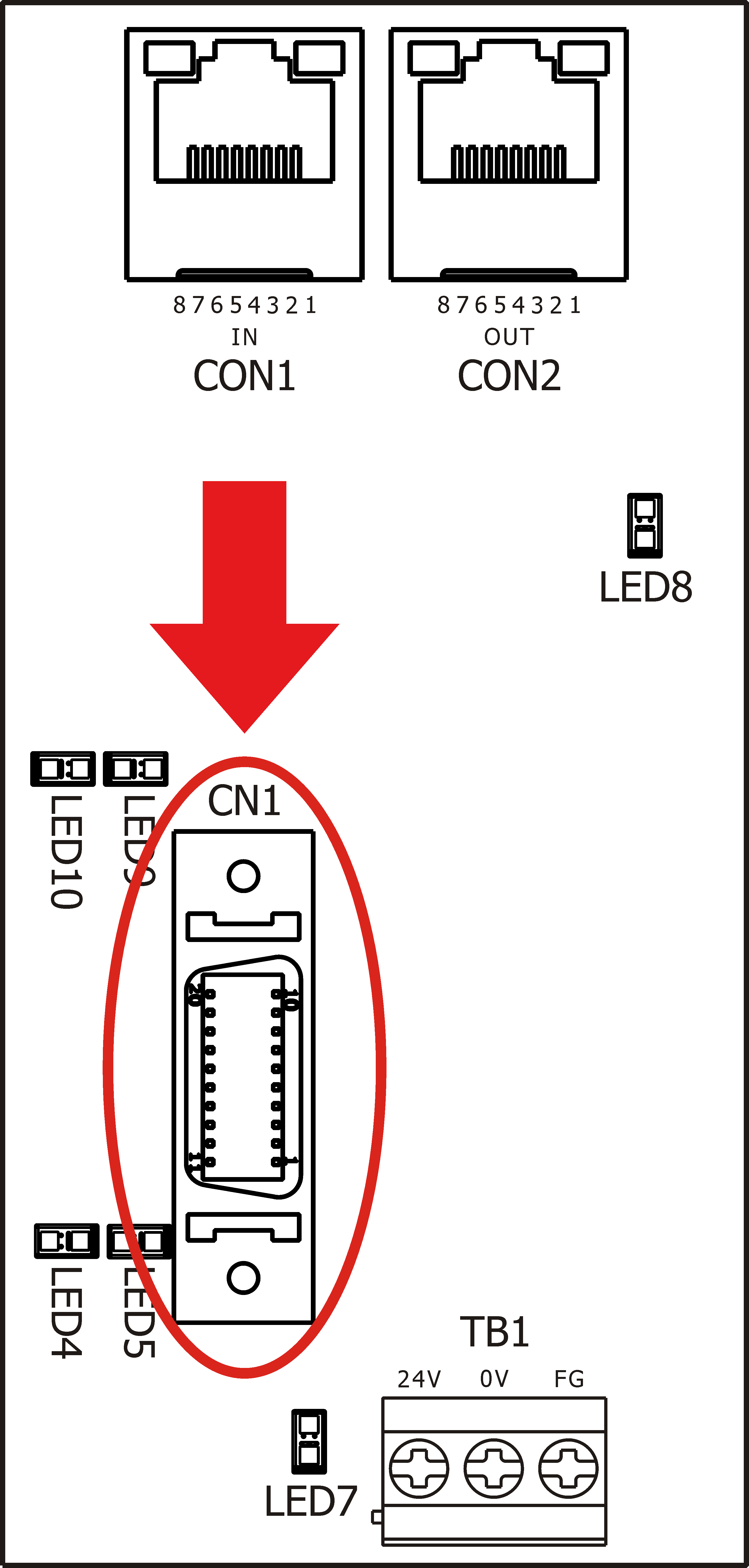
2.4.3 CN1: Servo Connector
CN1 servo connector use 3M connector and general interface servo connector to connect. Inside the connector it got velocity command, servo alarm, servo enable signal, servo index signal.
Pin |
Definition |
Explain |
1 |
Velocity command |
±10V analog output |
2 |
Velocity command reference point |
Velocity command reference |
3 |
Servo enable + |
Photocoupler output point |
4 |
Servo enable - |
Photocoupler output point |
5 |
Reserve + |
Photocoupler output point |
6 |
Reserve - |
Photocoupler output point |
7 |
A+ |
Encoder A+ input |
8 |
A- |
Encoder A- input |
9 |
B+ |
Encoder B+ input |
10 |
B- |
Encoder B- input |
11 |
C+ |
Axis index Encoder C+ input |
12 |
C- |
Axis index Encoder C- input |
13 |
Servo alarm 1 |
Limit to use NPN connection method (Provide 24G turn on for driver) |
14 |
Servo alarm 2 |
Limit to use NPN connection method (Provide 24G turn on for driver) |
15 |
Servo loading analogy input |
0V~10V analogy input |
16 |
Servo alarm common point |
Connect to driver, provide 24V |
17 |
VI |
I/O external power input point (If driver does not provide 24V power) |
18 |
VG |
I/O external power input point (If driver does not provide 24V power) |
19 |
5V |
Provide encoder or optical scaler with power (Power: 1W per axis) |
20 |
5GND |
Provide encoder or optical scaler with power (Power: 1W per axis) |

CN1 Servo Connector

CN1 Placement Drawing