2.6 Input Signal Character
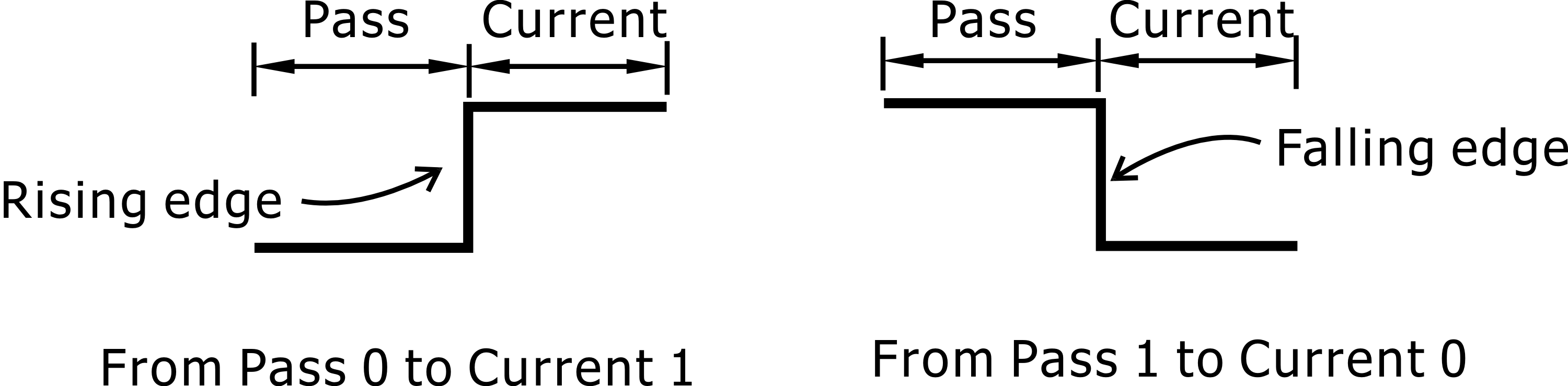
An electronic signal is 0 or 1, but also has rising signal 0→1 and falling signal 1→0, that is a pulse signal can have 4 states for application, as shown below.
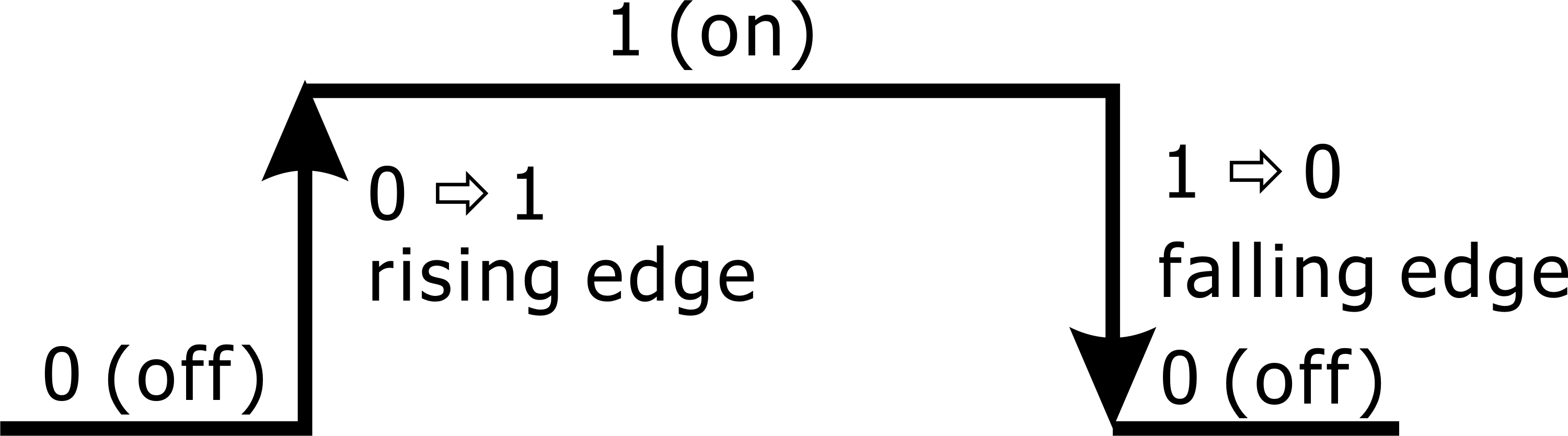
0 and 1 are level signals, these two states are using to detect auxiliary device on or off state, for example: coolant pump on or off is continue state, so PLC detects 1 or 0 to process coolant pump. We cannot using continue signal in panel key detects and bi-direction counter signal detects, because it will malfunction.
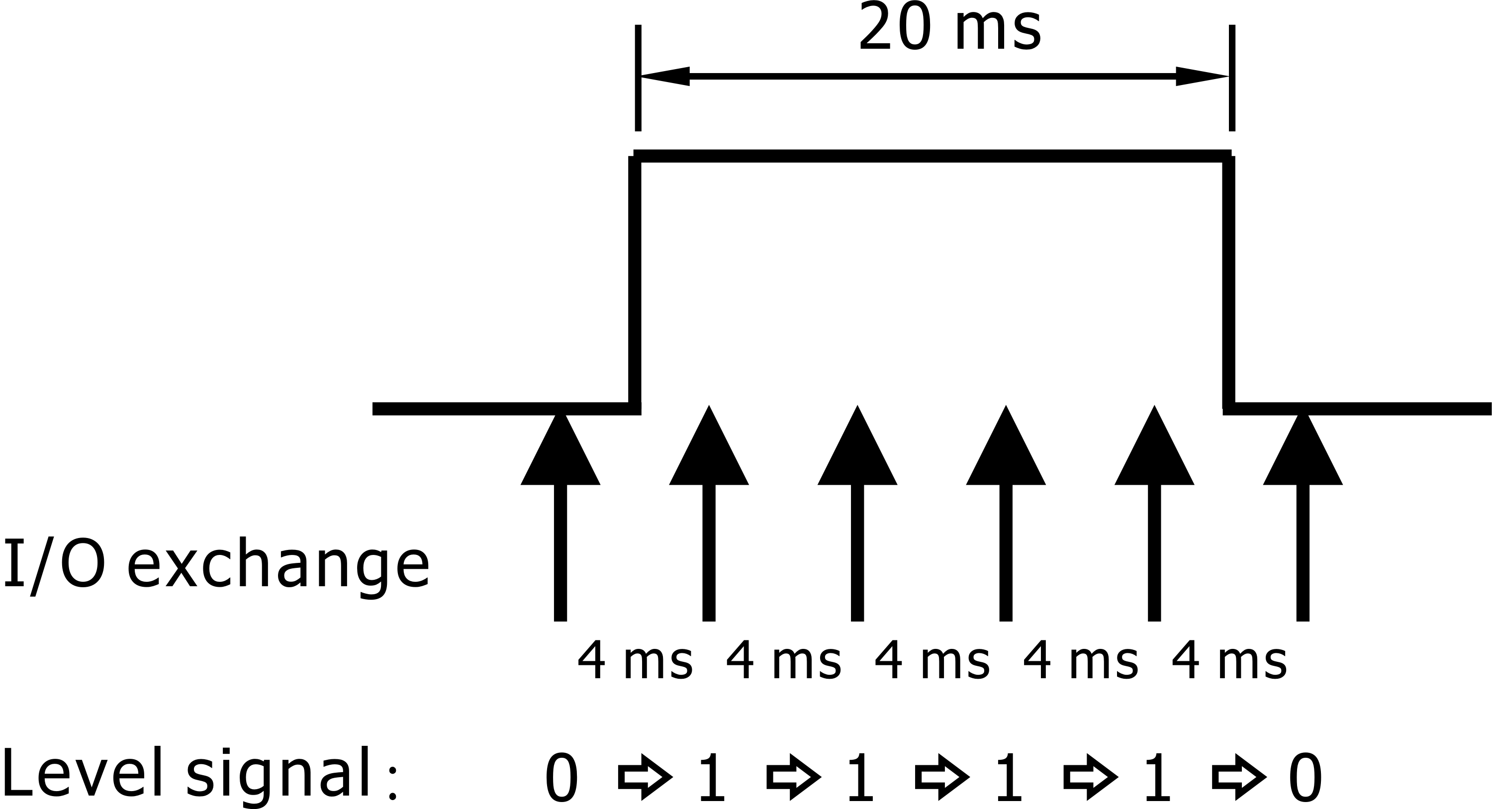
Described as follows: Because the PLC performs an I/O exchange every 4 ms, assuming that the reciprocating pushbutton that controls air pump is in the dual state Toggle mode, assuming a key press time of about 20 ms, then the I/O exchange will detect a signal four times in a row (mistakenly press the button four times), so the PLC will also process the key signal four times, resulting in the wrong result.
The following air pump to do the program description:
#define kiAirPump (plc.gdi[0].bit.bit02) //key input of air pump
#define oAirPump (plc.gdo[0].bit.bit01) //air pump control signal 1: on, 0: off
if(kiAirPump){
oAirPump = !oAirPump;
}
Result of procedure of oAirPump: 1 (on) →0 (off) →1 (on) →0 (off), this is wrong result.
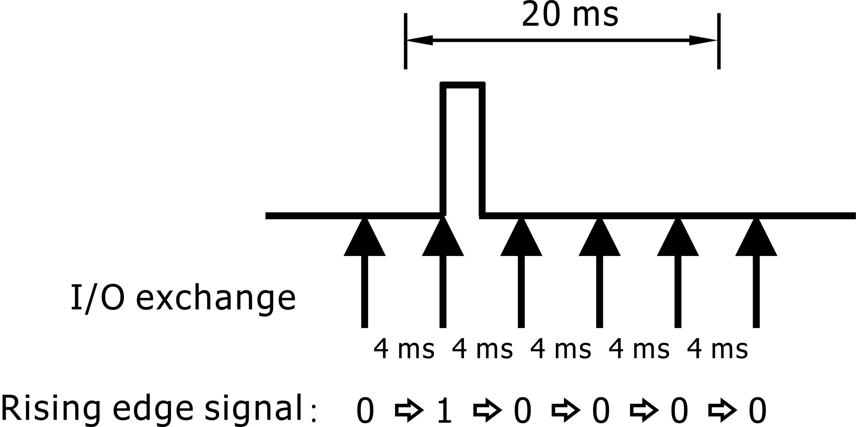
In this application, PLC processes signal only one time will meet function requirement that is PLC just processes rising edge of signal. Please refer to the following program example:
#define kiAirPump (riseGdi[0].bit.bit02) //rising edge key input of air pump
#define oAirPump (plc.gdo[0].bit.bit01) //air pump control signal 1: on, 0: off
if(kiAirPump){
oAirPump = !oAirPump;
}
oAirPump program processing results: 1 (on), press the button once the implementation of air pump.
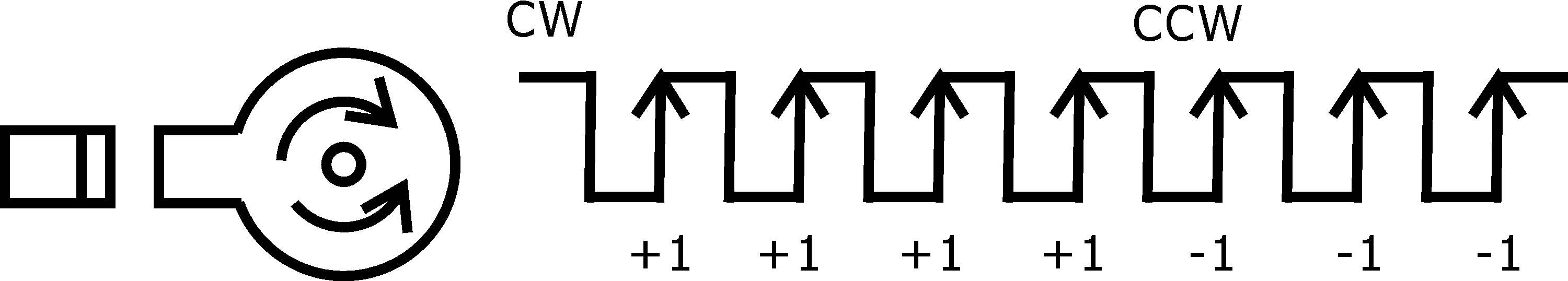
Signal direction counter can use the rising or falling edge to calculate the input signal, will not malfunction, as shown below:
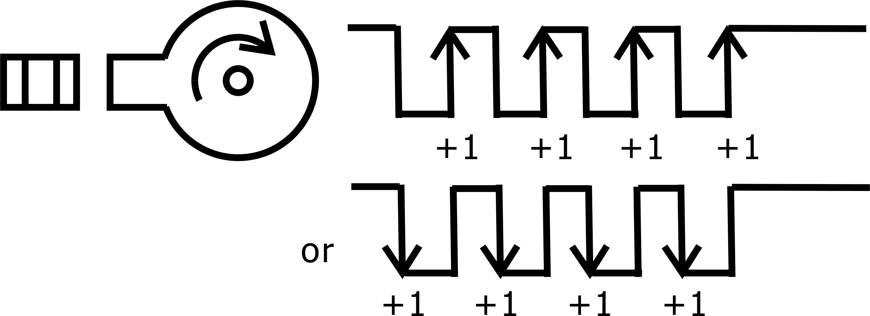
Bi-direction counter has the following two methods, you can get the correct signal.
If normal state of signal is 0, using the falling edge of the calculation will not be due to positive and negative misjudgment and count less once.
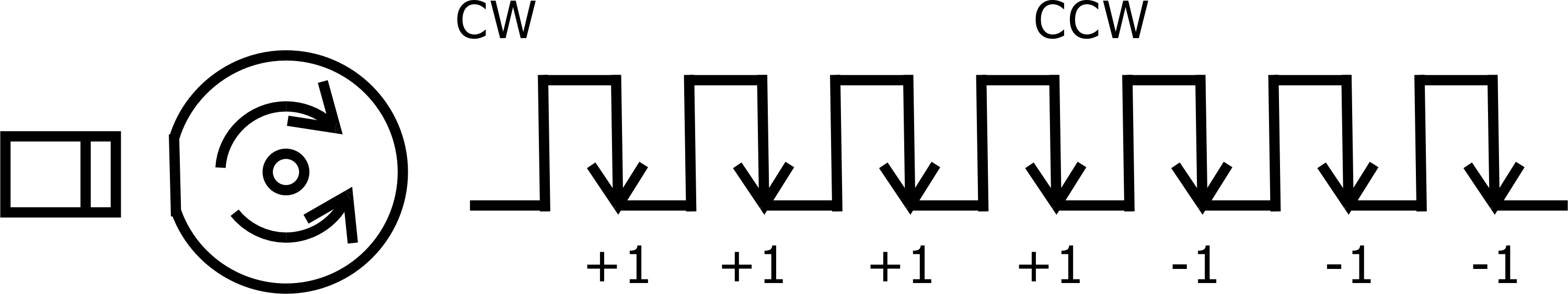
If normal state of signal is 1, using the rising edge of the calculation will not be due to positive and negative misjudgment and count less once.
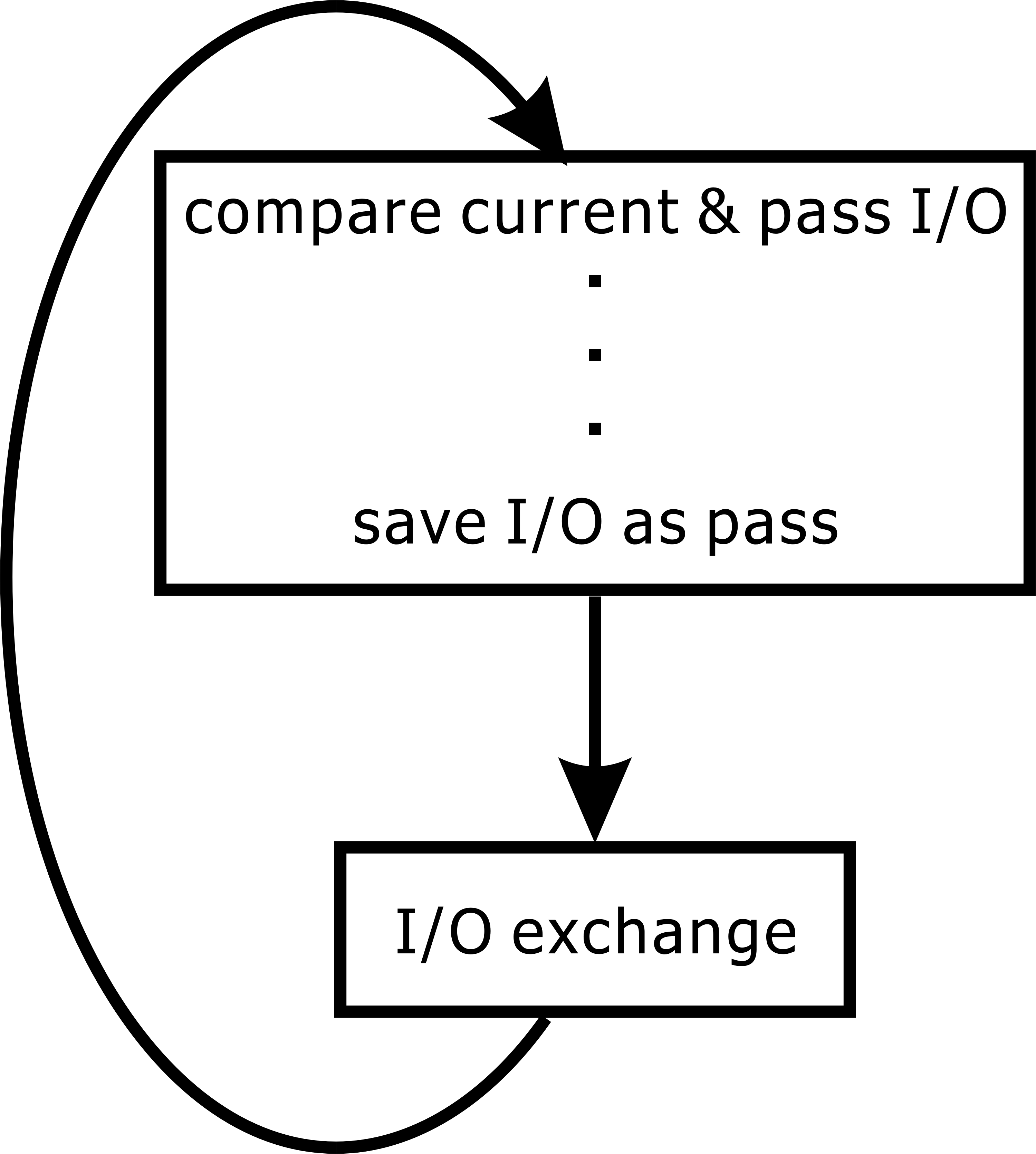
To fetch a rising edge or falling edge signal from input needs to compare current signal′s state and pass signal′s state.
For this purpose, we create oldGdi and riseGdi and fallGdi to save pass I/P state, rising edge of I/P and falling edge of I/P, these data structure same as I/P structure.
Example:
InPortGdi oldGdi0, oldGdi1, oldGdi2, oldGdi3, oldMpi0, oldMpi1, oldMpi2;
//For save pass I/P state
InPortGdi riseGdi0, riseGdi1, riseGdi2, riseGdi3, riseMpi0, riseMpi1, riseMpi2;
//For work out rising edge
InportGdi fallGdi2; //For work out falling edge
//Start of plcRun function
riseGdi0.iPort = (~oldGdi0.iPort) & plc.gdi[0].iPort; //rising edge for gdi0
riseGdi1.iPort = (~oldGdi1.iPort) & plc.gdi[1].iPort; //rising edge for gdi1
riseGdi2.iPort = (~oldGdi2.iPort) & plc.gdi[2].iPort; //rising edge for gdi2
riseGdi3.iPort = (~oldGdi3.iPort) & plc.gdi[3].iPort; //rising edge for gdi3
riseMpi0.iPort = (~oldMpi0.iPort) & plc.mpi[0].iPort; //rising edge for mpi0
riseMpi1.iPort = (~oldMpi1.iPort) & plc.mpi[1].iPort; //rising edge for mpi1
riseMpi2.iPort = (~oldMpi2.iPort) & plc.mpi[2].iPort; //rising edge for mpi2
fallGdi2.iPort = (oldGdi2.iPort) & (~plc.gdi[2].iPort; //falling edge for gdi2
//End of plcRun function save I/P state
oldGdi0.iPort = plc.gdi[0].iPort; //save gdi0 as pass state
oldGdi1.iPort = plc.gdi[1].iPort; //save gdi1 as pass state
oldGdi2.iPort = plc.gdi[2].iPort; //save gdi2 as pass state
oldGdi3.iPort = plc.gdi[3].iPort; //save gdi3 as pass state
oldMpi0.iPort = plc.mpi[0].iPort; //save mpi0 as pass state
oldMpi1.iPort = plc.mpi[1].iPort; //save mpi1 as pass state
oldMpi2.iPort = plc.mpi[2].iPort; //save mpi2 as pass state