1 PLC Works in System
Within the INCON-M84/M86/M86R controller, two system programs are running simultaneously:
1. NC system program
2. PLC system program
Although these two system programs operate independently, but through the internal data structure to communicate and coordinate the actions of each other.
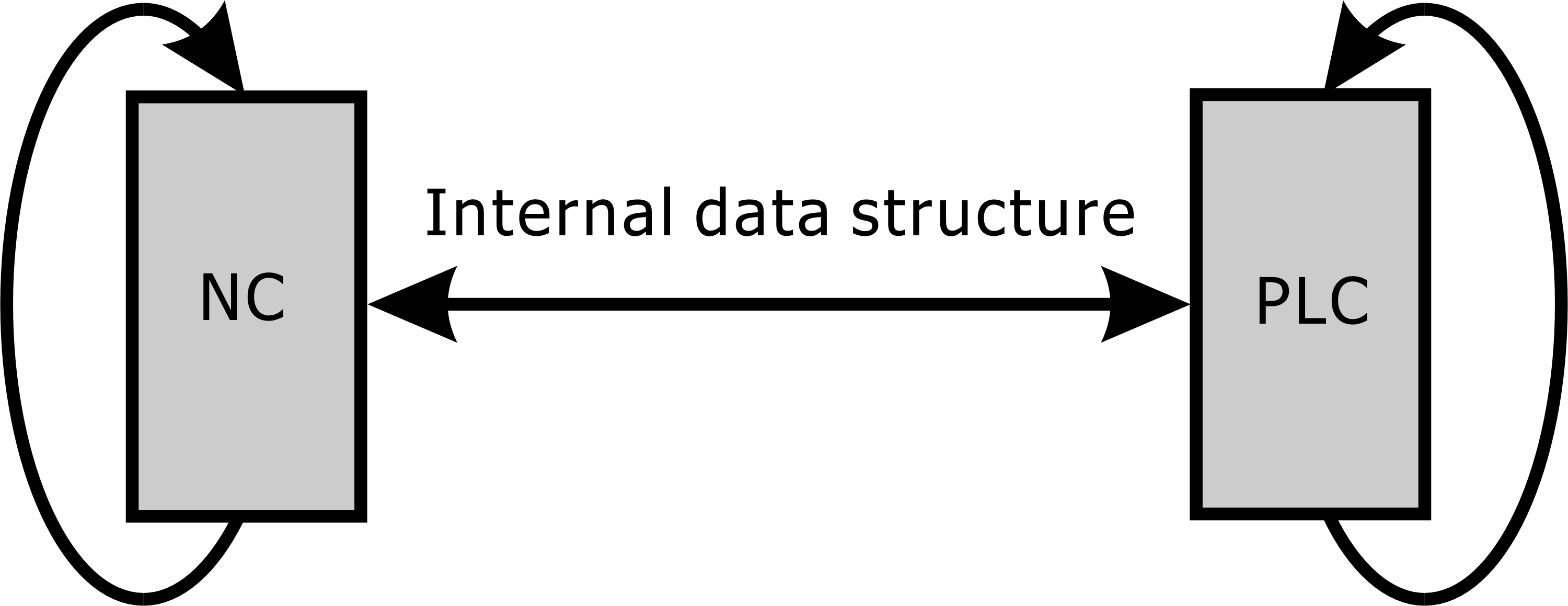
The system program of NC has been developed completely by INTEK, but users can input or edit CNC part programs on INCON-M84/M86/M86R. NC system program will be based on processing program content to be interpreted, implemented, calculated, the control path and response status. If it is necessary for the PLC to help process the project, the PLC will be informed through the internal data structure to process and obtain a PLC reply.
The outputs of PLC are divided into two groups: one does not care about output result and the other cares about output result from devices controlled by the outputs. The inputs of PLC are divided into two groups: one does not reply inputs and the other replies inputs.
Note: |
The "Device" in the figure below can be expressed as auxiliary equipment or NC communication interface. |
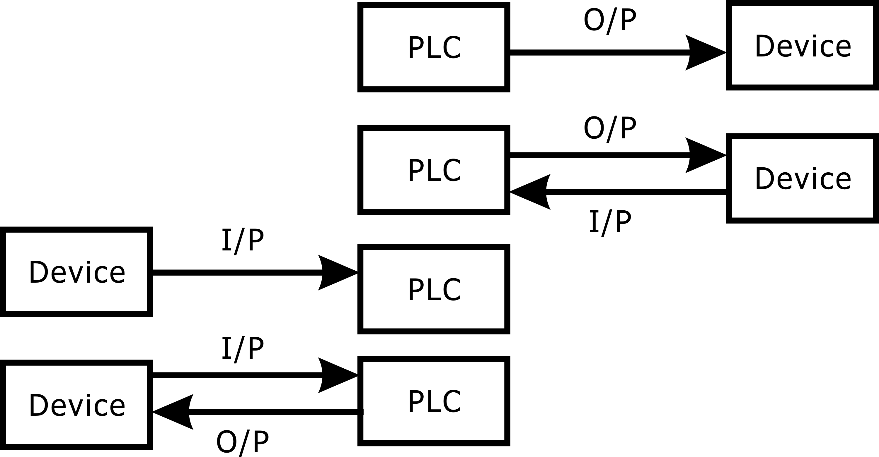
If the input and output signals to be replied, there is a certain timing, the two sides can communicate according to the timing can really complete the action. We call this communication timing a protocol.
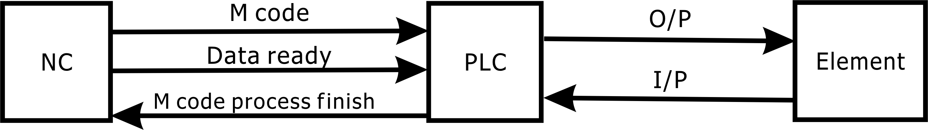
The most common processing between NC and PLC is the processing related to M code, S code and T code. The processing of these codes is completed through the communication interface between NC and PLC. After the PLC finishes disposing, it will control the controlled components. After the components reply (or do not need to be replied), it replies to the NC finished processing.
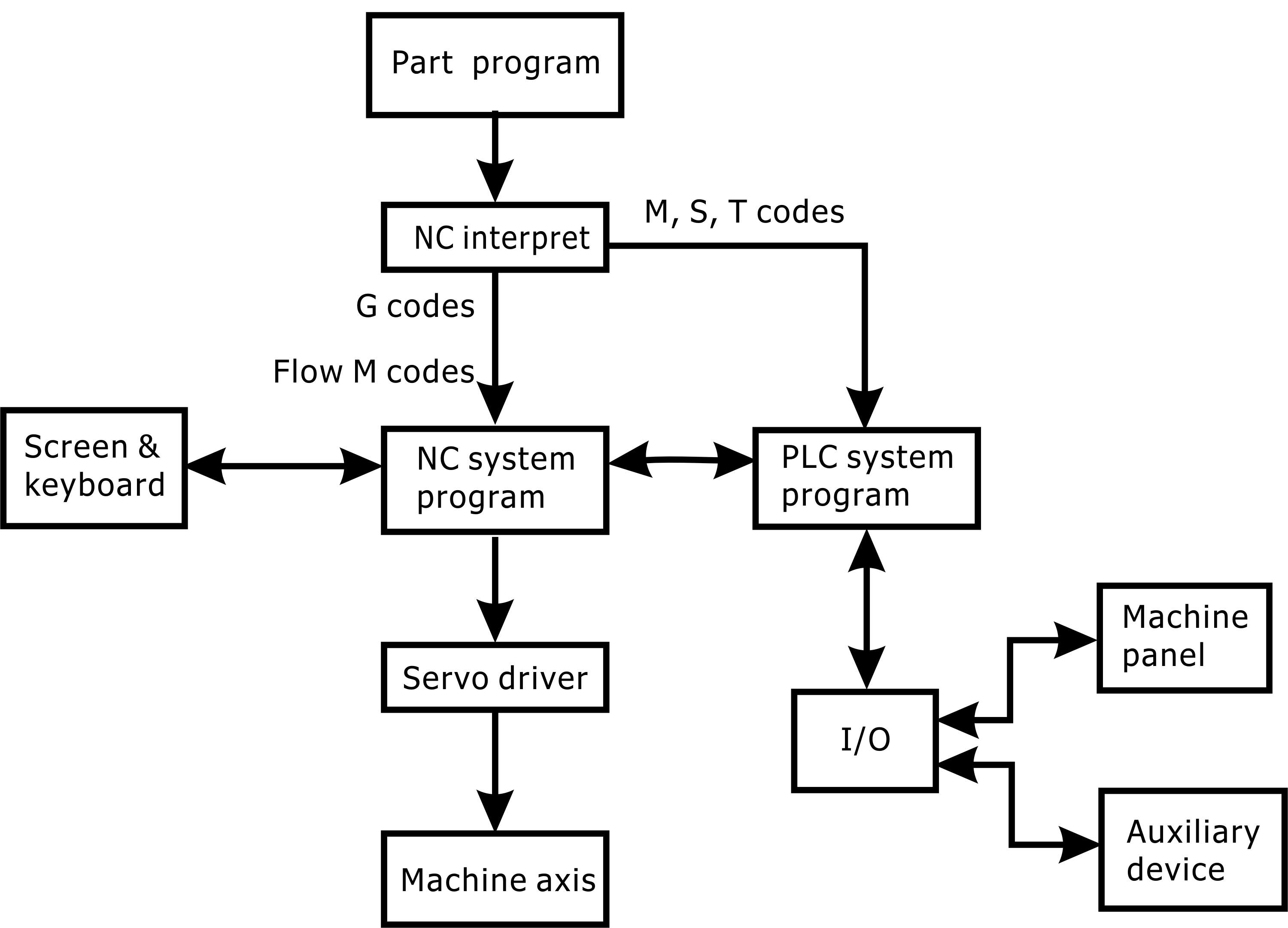
The programming code used by the program is the standard ISO G, M, S, T code. Among them, G codes are related to the axial movement of the machine; Some M codes are related to the processing program flow; Other M-code, S-code and T-code, which have nothing to do with the process flow, are related to the movement of the auxiliary equipment of the machine.
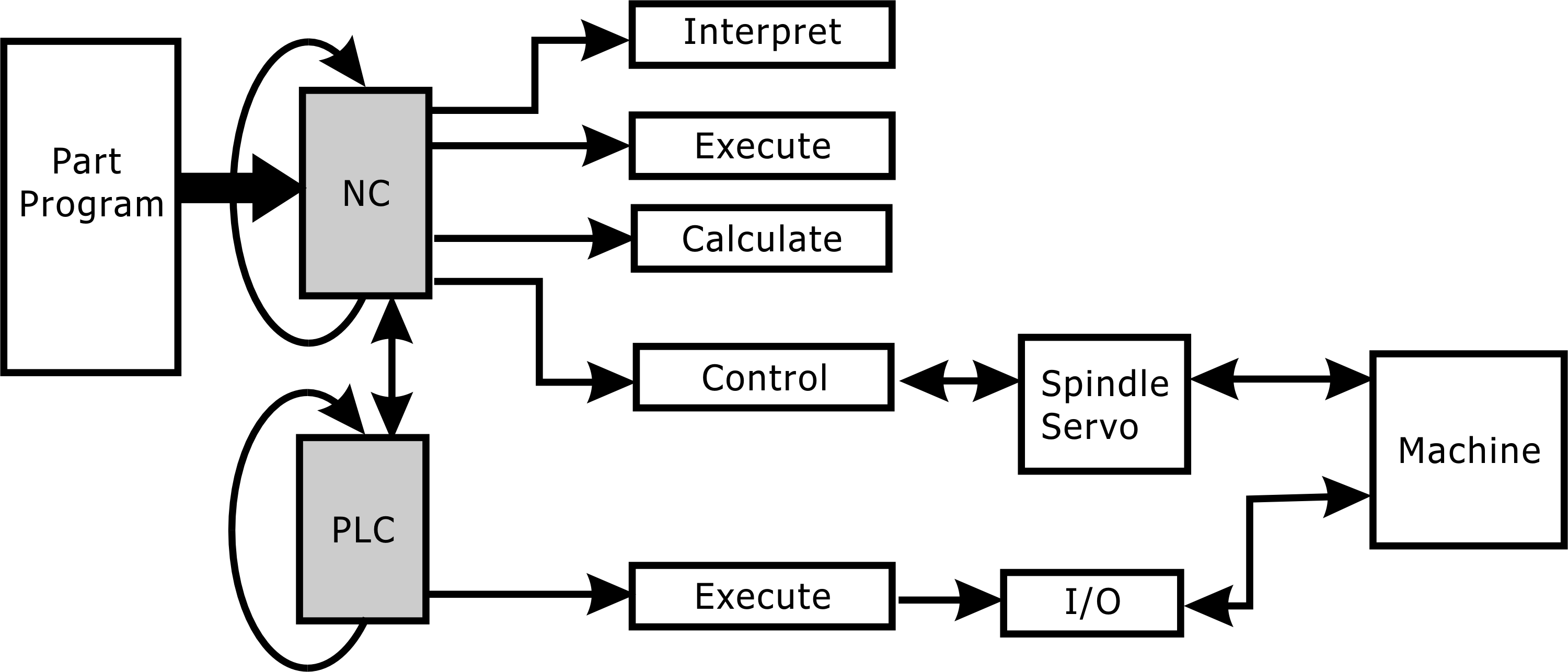
When the processing program is interpreted, NC will determine the M, S, T code processed by the PLC, and then deliver the PLC processing, waiting for the PLC reply processing completed; When the NC executes the G code, it will refer to the current state of the PLC for further processing (ex: override rate). The diagram is showing as below is flow of CNC part program.
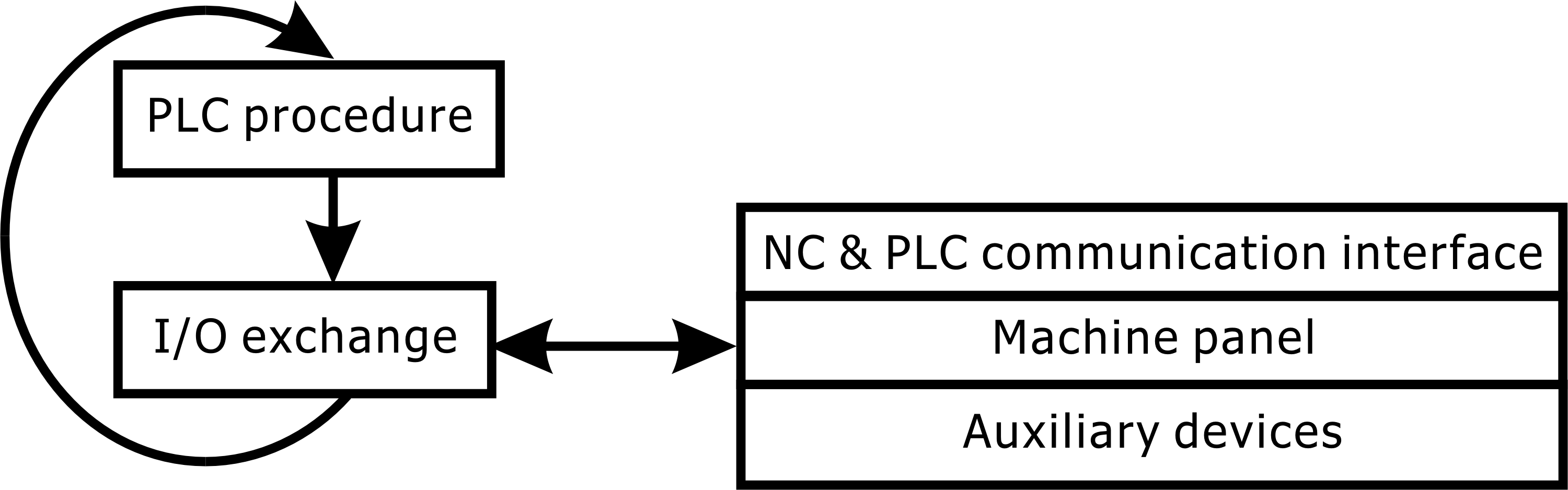
INCON-M84/M86/M86R PLC processes M code, S code, T code, machine panel and auxiliary device and outputs result to communicative interface between NC task & PLC task and control machine panel and auxiliary device by I/O exchange. In the meantime PLC reads machine panel, auxiliary device and communicative interface states as reference for next cycle of PLC procedure.
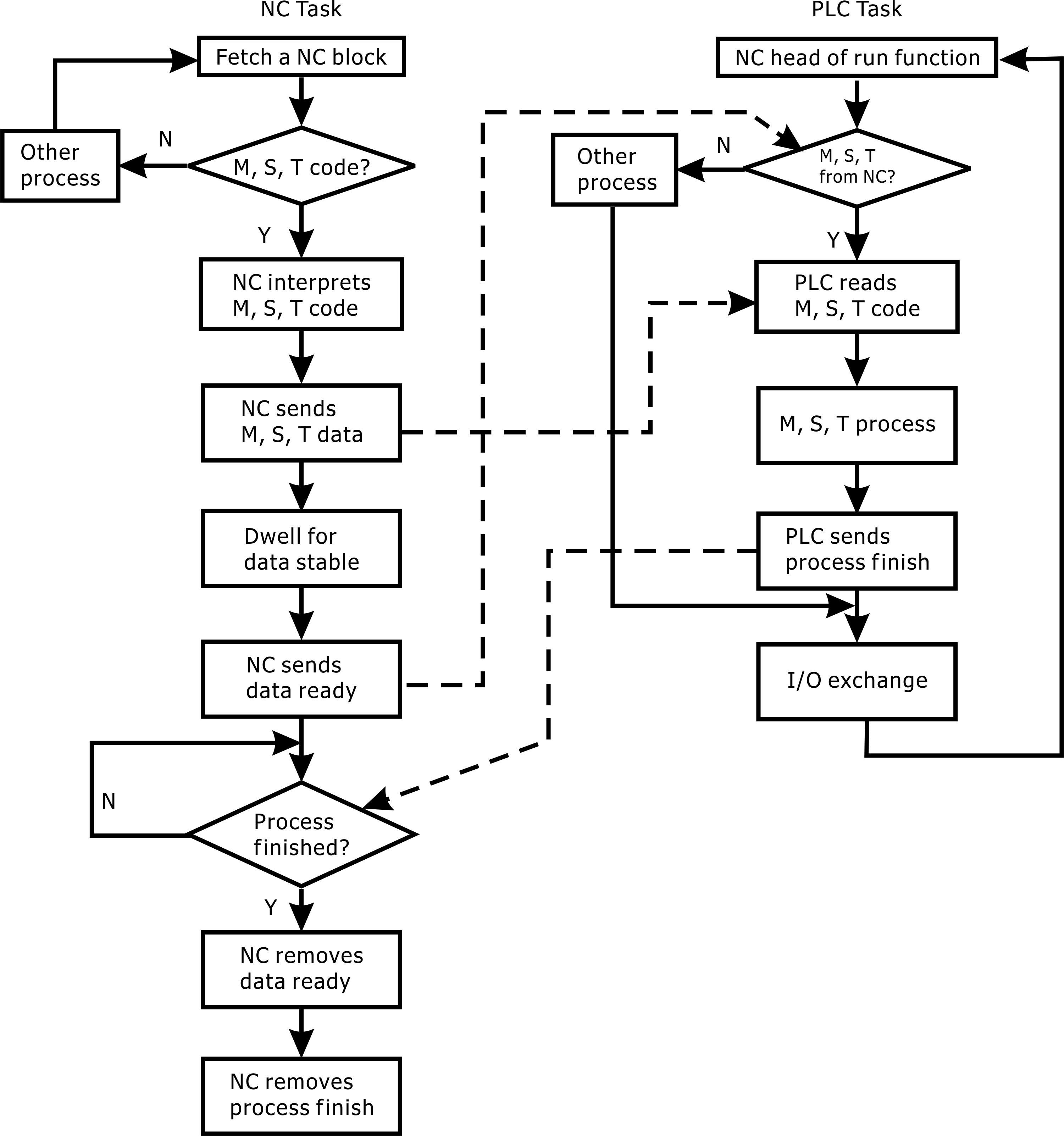
The following is a flowchart illustrating the timing between NC and PLC:
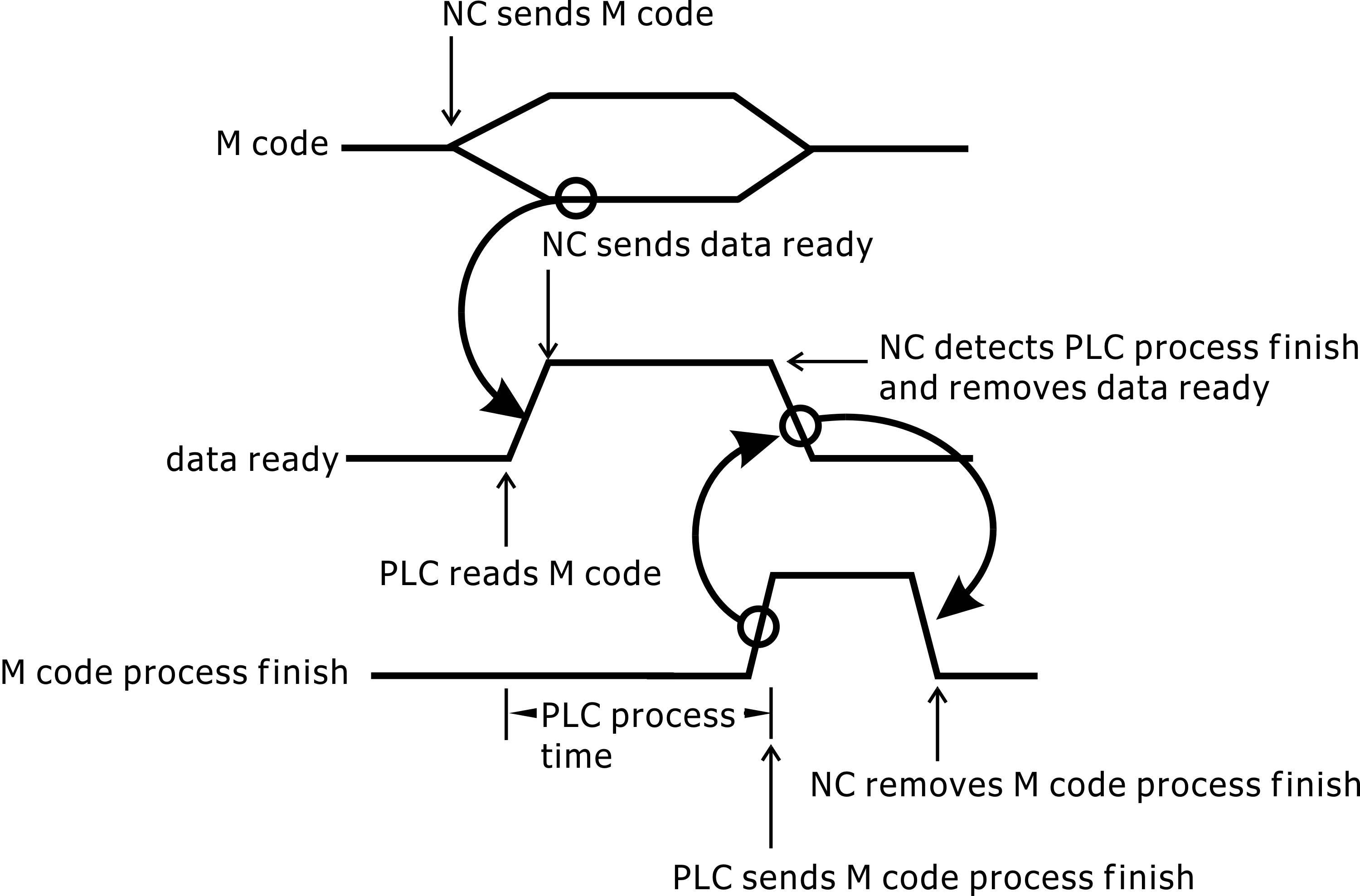
The agreement between NC and PLC is done in time series, the timing diagram is as follows:
We have already understood NC task & PLC task how to work, and we are looking an example of M03 (spindle CW) and M05 (spindle stop) events.
The information structure of M code data, M code preparation and M code processing in INCON-M84/M86/M86R controller is as follows:
plc.mCode.data // M code data
plc.mCode.flag // M code data ready
plc.mCode.finish // PLC M code process finish
An inverter controls the spindle motor, and inverter is controlled by PLC output, inverter has two outputs for speed reach and zero speed.
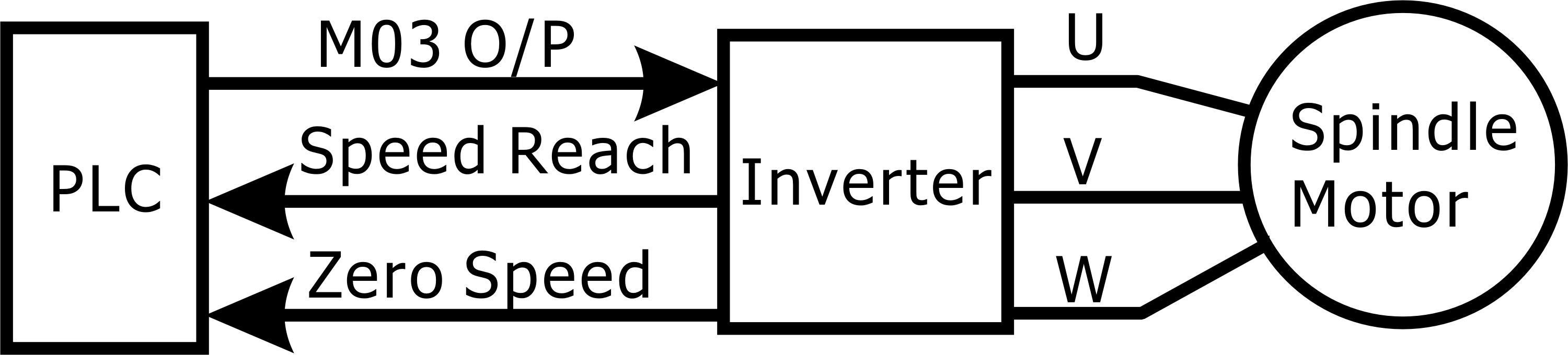
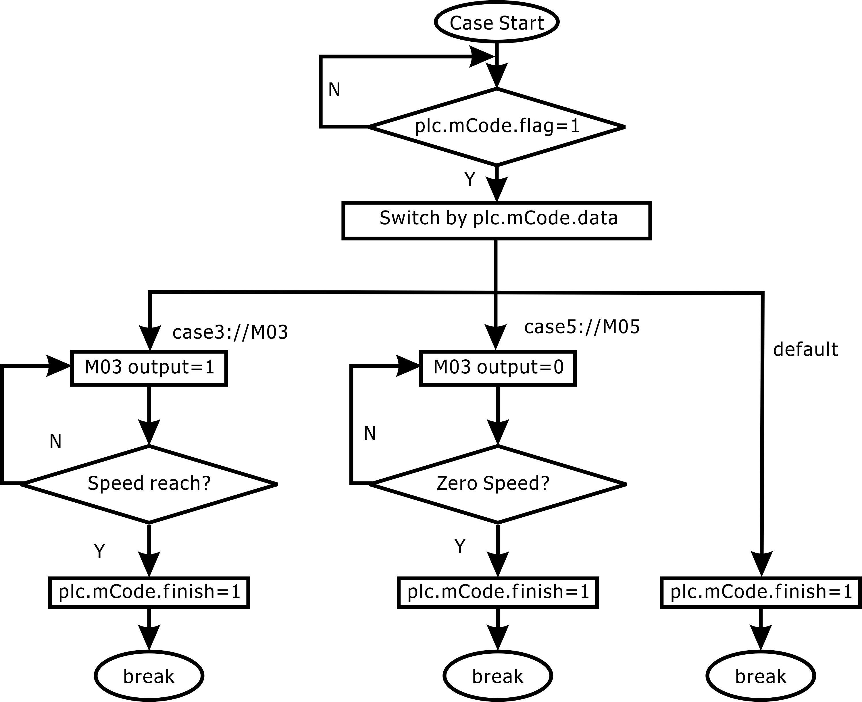
M03 event and M05 event are processed by PLC procedure. When plc.mCode.flag becomes 1, PLC reads plc.mCode.data then processes M03 or M05, if plc.mCode.data is 3, PLC turn on M03 output and waiting Speed reach signal from Inverter. After PLC received Speed reach "on" signal then sends plc.mCode.finish. If plc.mCode.data is 5, PLC turn off M03 output and waiting Zero speed signal from Inverter. After PLC received Zero Speed "on" signal then sends plc.mCode.finish.
We can draw M03 event flow chart and M05 event flow chart before we write procedure by C language. The flow chart will help you to analyze event and easy to maintain.
C language for M03 and M05 event:
#define speed_reach (plc.gdi[0].bit.bit00) // speed reach from inverter is I0
#define zero_speed (plc.gdi[0].bit.bit01) // zero speed from inverter is I1
#define m03_output (plc.gdo[0].bit.bit00) // M03 output is O1
if(plc.mCode.flag){
switch(plc.mCode.data){
case 3:
m03_output = 1;
if(speed_reach)
plc.mCode.finish = 1;
break;
case 5:
m03_output = 0;
if(zero_speed)
plc.mCode.finish = 1;
break;
default:
plc.mCode.finish = 1;
break;
}
}
The INCON-M84/M86/M86R PLC is fix loop task; the cycle time of loop is 4 ms. An I/O exchange will execute at end of loop.
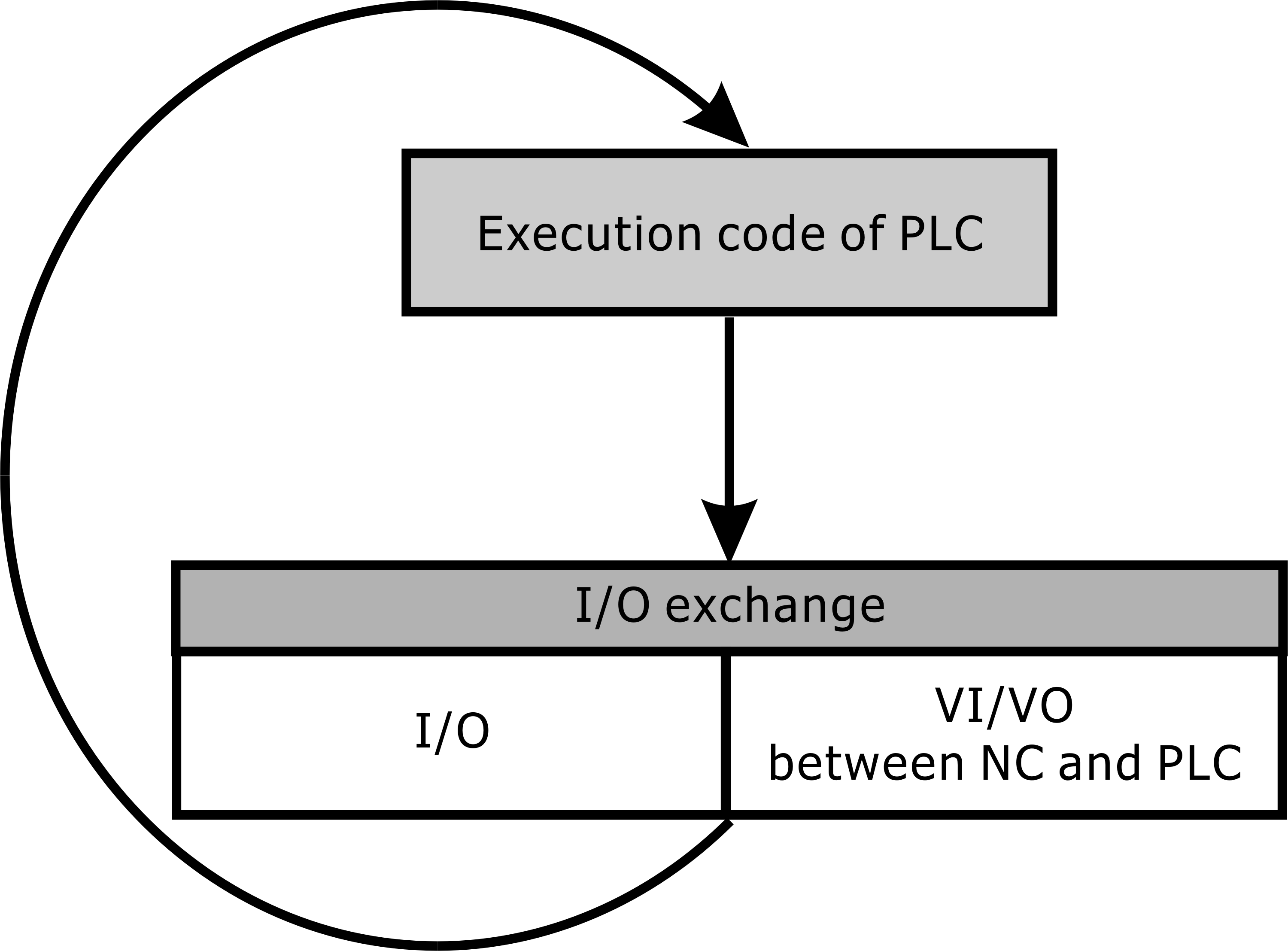
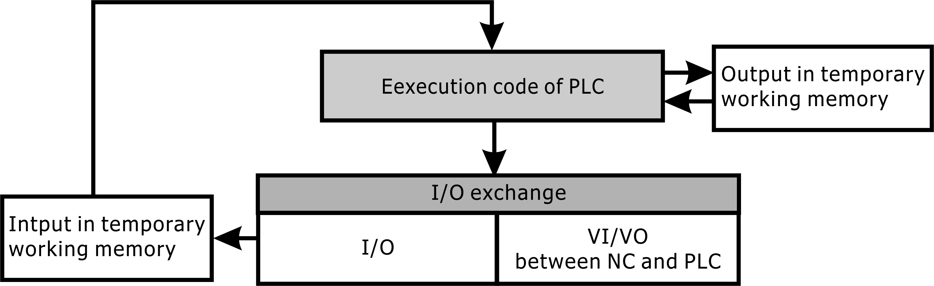
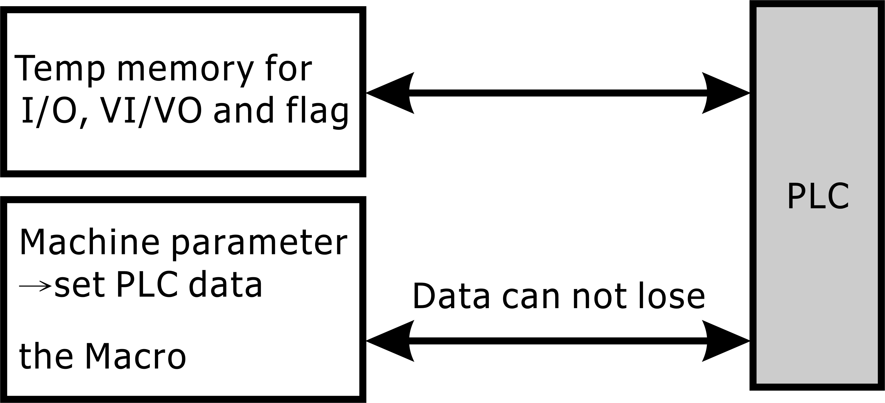
The I/O exchange section has two parts, the first is the actual I/O (input/output) and the second is the VI/VO (virtual input/virtual output) communication between the NC and the PLC. When I/O exchange is executed, physical input and virtual input will save in temp memory for next PLC cycle. A temp output memory keeps tracing PLC procedure output, and I/O exchange puts instant output to physical output and virtual output.
I/O temporary area will disappear due to shutdown data, can not be saved to the next boot, but some of the information must be retained as a parameter, or status; Therefore, these do not allow the loss of information to be stored. INCON-M84/M86/M86R controller "mechanical parameters → set PLC data" is a data backup sub-area can be stored in addition to share with the NC macro variable data area is also a data backup sub-area. INCON-M84/M86/M86R controller can use these two areas as PLC data backup area.
As can be seen from the description of this chapter, the PLC of INCON-M84/M86/M86R controller is the same as the PLC of general controller, but because of the PLC using high-end language C language as a PLC program development tools, INCON-M84/M86/M86R controller PLC has a higher efficiency of the execution speed. The C language syntax used by PLC in INCON-M84/M86/M86R controllers avoids endless loop errors when "do", "while", and "for" loopbacks are not executed. If you want to learn more about C language grammar, you can purchase books to read.