![]() 5.4 Spline Interpolation
5.4 Spline Interpolation
The CNC program determines the path of the tool machining movement and requires the CNC to follow the program path exactly. The G01 command specifies the path of the straight line. When the spline interpolation function is enabled and the INCON-M86R controller is allowed to execute the G01 command, the path is made using the path error between the point and point specified by the curve.
The purpose of the contouring interpolation is to speed up the execution of the program, or to make the movement more smooth, or to use a curve to connect the path points, but because the path is not the original straight path, the user must understand the role of the spline interpolation, to determine Whether to start or set the size of the error.
Parity interpolation is applied to consecutive G01 commands. If there are other commands in the middle, there is no effect. For example, there is M code or G11.60 mode in the middle. Therefore, it is suitable for rough and angled programs.
INCON-M86R provides two kinds of spline interpolation. The first one is the error mode. The path is determined by the user to specify the path error. The second is the over point mode. The specified path must pass through the position of G01, but between the point and the point. Allows a curved path, which is determined by INCON-M86R.
The user can set the pattern and error of the simulated line interpolation in three ways. The installed machine and the user use the machine as required.
(1) |
From the mechanical parameters "Advanced → Motion and Speed → Spline Tolerance". |
(2) |
From the mechanical parameters "High Speed High Precision Profile → SplineTol". |
(3) |
Use G10.67 Pxxx in the program to start the error mode line interpolation, and xxx is used to specify the error value. Use G10.67 P0 or G11.67 to stop the action of the spline interpolation. |
(4) |
G10.68 is used in the program to start the over-point mode simulation interpolation and canceled with G11.68. |
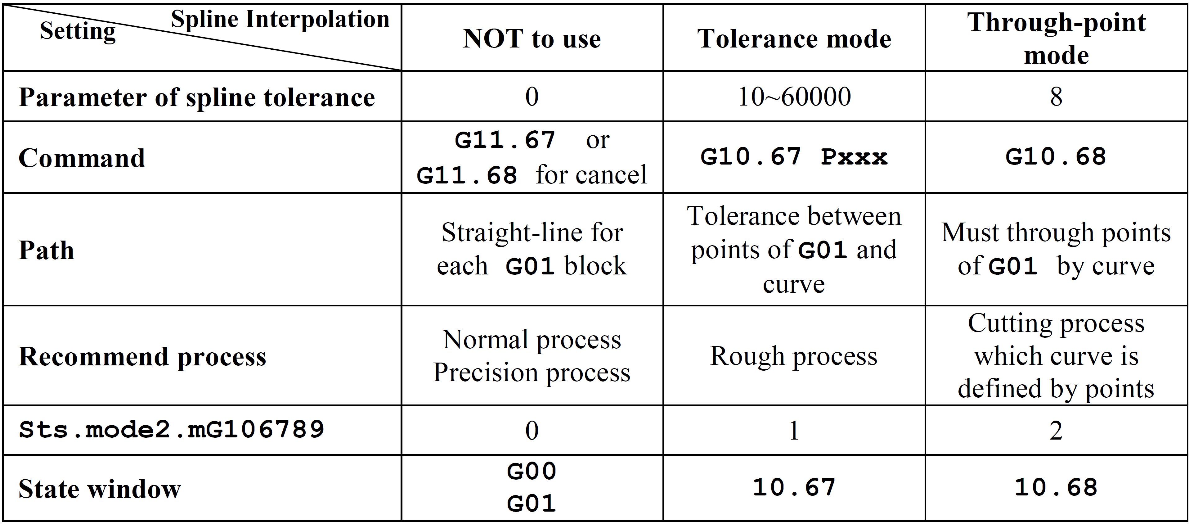
Setting of the tolerance of the spline line interpolation
(1) |
This value sets the tolerance for the spline interpolation, and its unit is um, ranging from 0 or 8 or 10 to 60000. |
(2) |
When the tolerance value is set to 0, it means that the spline interpolation is not started, and when this value is 8, it specifies that the over-point mode spline interpolation is used. The remaining 10~60000 specify the use of the error mode spline interpolation. |
Error mode spline interpolation
(1) |
When the error pattern is initiated by the spline interpolation, the CNC controller internally replaces the straight line with an approximate curve to achieve a smoother movement, but the path and the original linear motion path will form an error, and the error does not exceed the set tolerance value. |
(2) |
It is recommended that the user use spline interpolation in the condition that the roughing or confirming error range is within the allowable range. If you are unsure of the error value you want to use, you can start the test with 100 and then increase or decrease the result. |
Cross-point pattern spline interpolation
(1) |
INCON-M86R uses the G01 point of the appropriate curve connection program when the over-point pattern mitigation starts. |
(2) |
Over-point mode is suitable for program application of cutting processing mode. The curve is defined by a limited number of points. The user can increase the point to approximate the curve to be processed. |
Spline interpolation state representation
If the PLC signal Sts.mode2.mG106789 has a value of 0, it means that the spline interpolation is not used. When this value is 1, it means that the error mode is used for the spline interpolation. When the value is 2, it means that the point pattern is used for the spline interpolation.
When the spline interpolation is active, G00 in the status window will switch to display G10.67 or G10.68. At this time, the TP value in the status window will flash, representing the sub-process number of the interpolation.
spline line interpolation summary
The following is an example program and path diagram:
(1) sample program
%
G11.67 ;Cancel the spline interpolation
M97 P0001
G10.67 P700 ;Start error mode spline interpolation, error 700
M97 P0001
G10.68 ;Start point pattern imitation interpolation
M97 P0001
M30
O0001
G90 G54
G00 X0 Y0
G01 X10. F1000
Y10.
X0
Y0
M99
(2) Path diagram
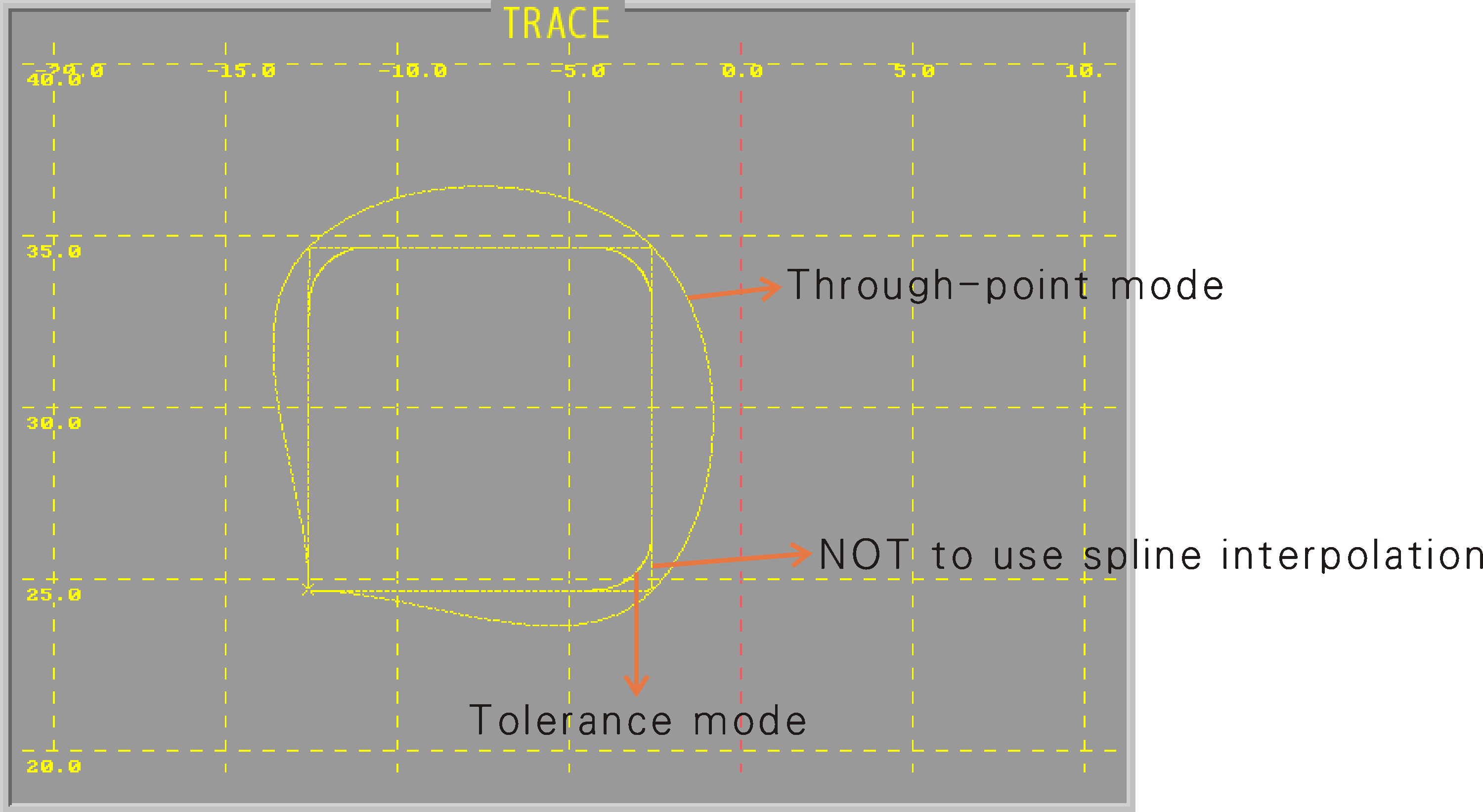
Path of spline interpolation
Note: |
For details on the setting of the machine parameters, please refer to M84/M86/M86R integration manual. |