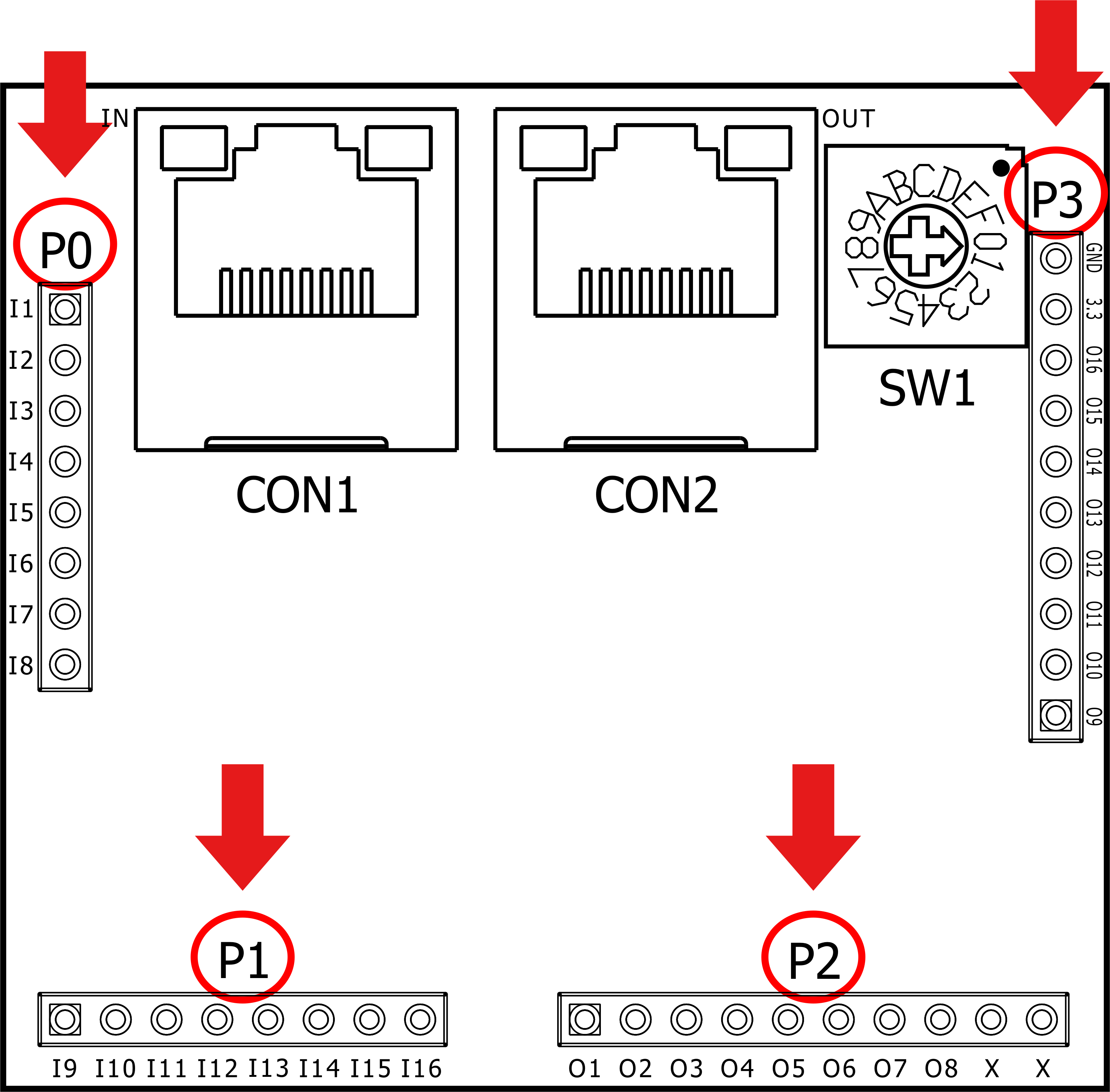
2.6.2 P0~P3 Pin Stick
Through the pin sticks and connection with the customer's device (usually are circuit board) of the P0~P3 of the ENU and when the pin stick is compatible with the INET communication unit of INCON-M470~M675 CNC Controller, the pin stick of each connector is as following:
Pin |
P0-I1 |
P0-I2 |
P0-I3 |
P0-I4 |
P0-I5 |
P0-I6 |
P0-I7 |
P0-I8 |
Explain |
Digital input point 1 |
Digital input point 2 |
Digital input point 3 |
Digital input point 4 |
Digital input point 5 |
Digital input point 6 |
Digital input point 7 |
Digital input point 8 |
Pin |
P1-I9 |
P1-I10 |
P1-I11 |
P1-I12 |
P1-I13 |
P1-I14 |
P1-I15 |
P1-I16 |
Explain |
Digital input point 9 |
Digital input point 10 |
Digital input point 11 |
Digital input point 12 |
Digital input point 13 |
Digital input point 14 |
Digital input point 15 |
Digital input point 16 |
Pin |
P2-O1 |
P2-O2 |
P2-O3 |
P2-O4 |
P2-O5 |
P2-O6 |
P2-O7 |
P2-O8 |
P2-O9 |
P2-O10 |
Explain |
Digital output point 1 |
Digital output point 2 |
Digital output point 3 |
Digital output point 4 |
Digital output point 5 |
Digital output point 6 |
Digital output point 7 |
Digital output point 8 |
Empty pin |
Empty pin |
Pin |
P3-O9 |
P3-O10 |
P3-O11 |
P3-O12 |
P3-O13 |
P3-O14 |
P3-O15 |
P3-O16 |
P3-3.3V |
P3-GND |
Explain |
Digital output point 9 |
Digital output point 10 |
Digital output point 11 |
Digital output point 12 |
Digital output point 13 |
Digital output point 14 |
Digital output point 15 |
Digital output point 16 |
Provide 3.3V power to ENU from customer Device |
3.3V power ground |

P0~P3 Placement Drawing