2.7.3 CON4, CON5: Handwheel Connector
Pin |
Definition |
Explain |
||||
1 |
Axis selection input point 1 |
Through PLC set the corresponding axis |
||||
2 |
Axis selection input point 2 |
Through PLC set the corresponding axis |
||||
3 |
Axis selection input point 3 |
Through PLC set the corresponding axis |
||||
4 |
Axis selection input point 4 |
Through PLC set the corresponding axis |
||||
5 |
Axis selection input point 5 |
Through PLC set the corresponding axis |
||||
6 |
Axis selection input point 6 |
Through PLC set the corresponding axis |
||||
7 |
A+ |
Handwheel signal A+ input |
||||
8 |
A- |
Handwheel signal A- input |
||||
9 |
B+ |
Handwheel signal B+ input |
||||
10 |
B- |
Handwheel signal B- input |
||||
11 |
Z+ |
Handwheel signal Z+ input (General handwheel without this signal) |
||||
12 |
Z- |
Handwheel signal Z- input (General handwheel without this signal) |
||||
13 |
Handwheel step width input point 1 |
Through PLC set the corresponding magnification |
||||
14 |
Handwheel step width input point 2 |
Through PLC set the corresponding magnification |
||||
15 |
Handwheel step width input point 3 |
Through PLC set the corresponding magnification |
||||
16 |
n/c |
Empty |
||||
17 |
VI |
+24V input power from external I/O, the power cannot use the same power supplier as EKU. |
||||
18 |
VG |
|
||||
19 |
5V |
Provide handwheel 5V power (Power: 1W) |
||||
20 |
5V GND |
Provide handwheel power 5V power ground (Power: 1W) |
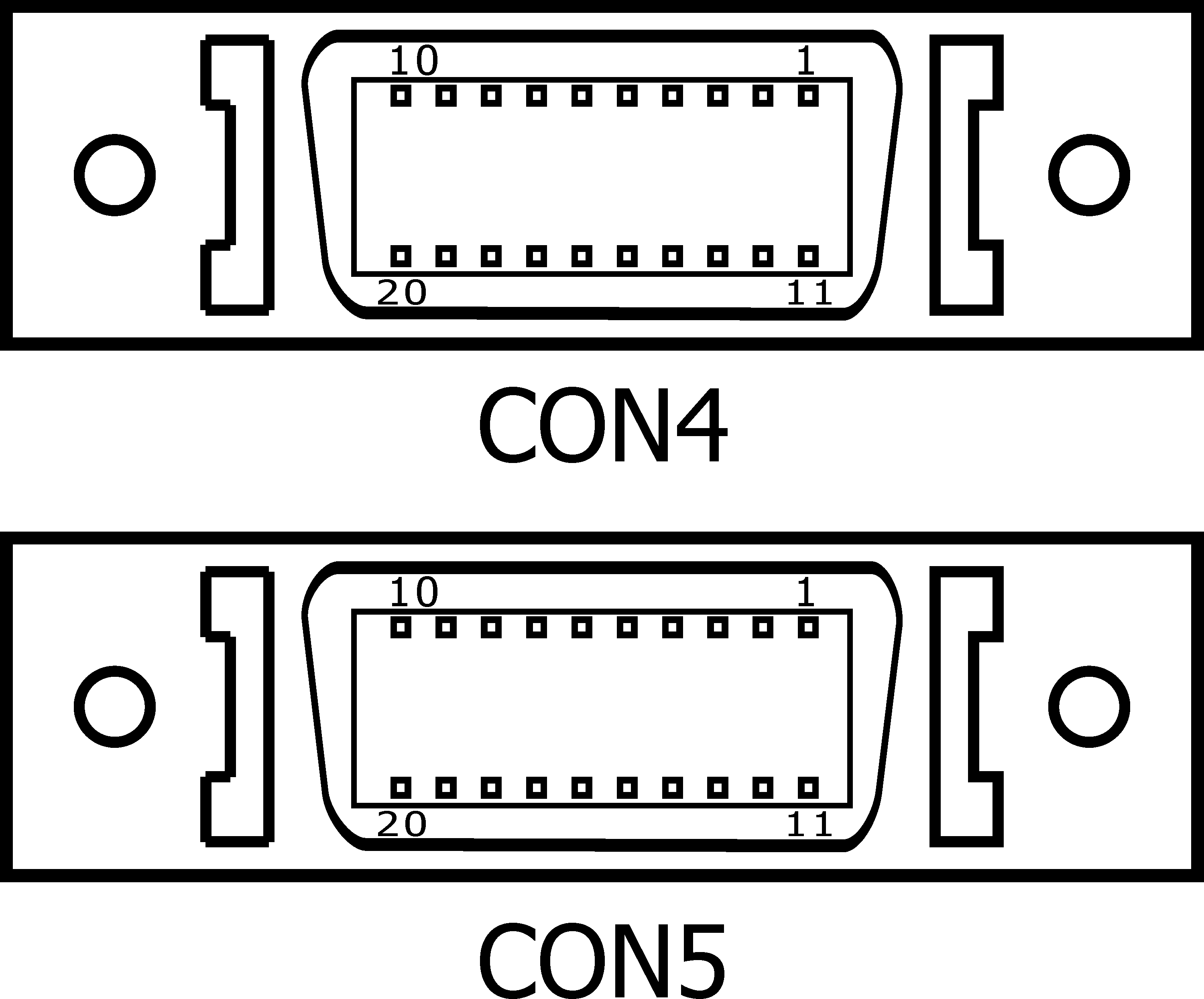
CON4, CON5 Handwheel Connector
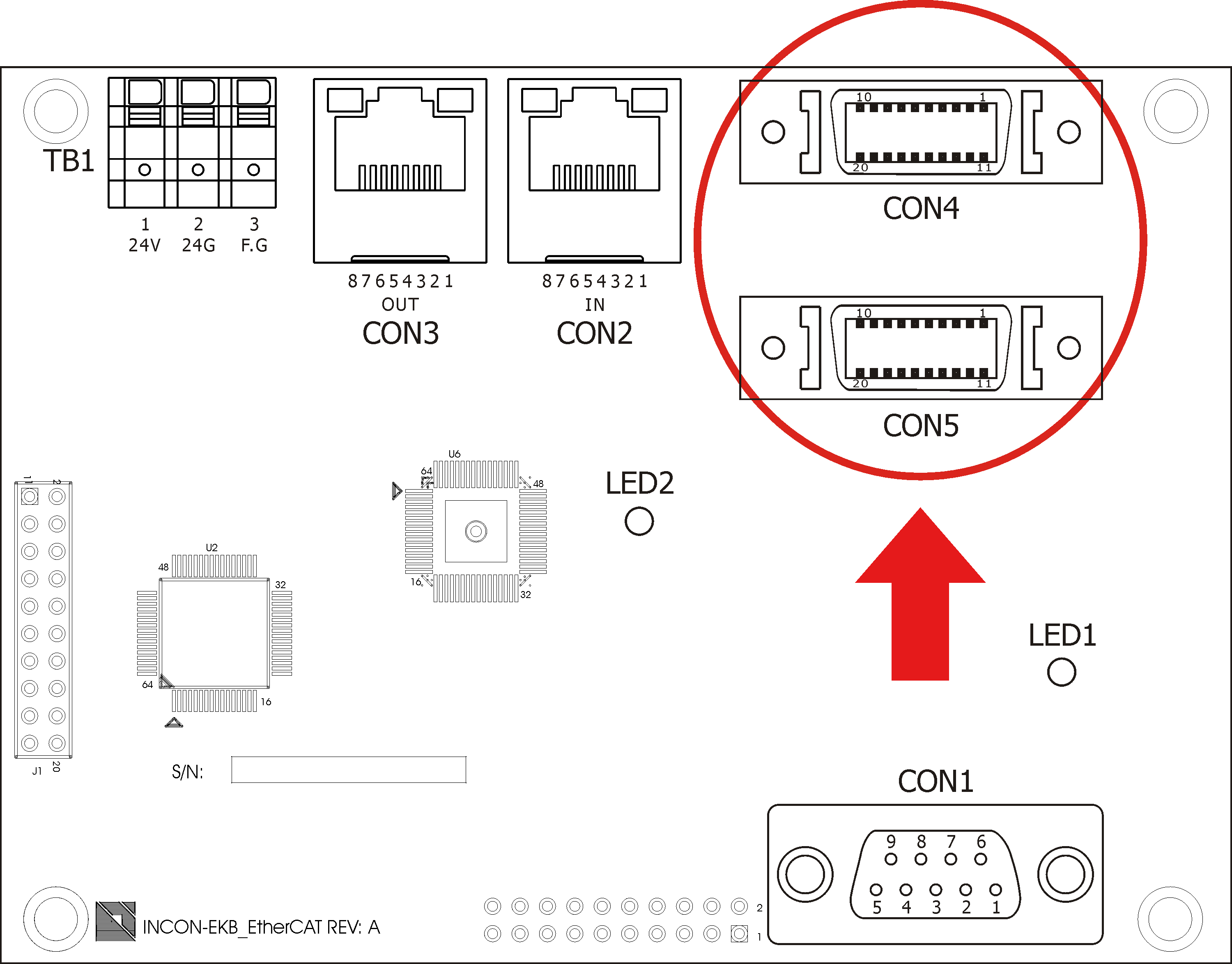
CON4, CON5 Placement Drawing