2.9.2 Definition of Each Connector and Contact
Power Terminal
TB1 provides the connection to DC 24V. Please use the same power source of controller host. The LED1 would light up as the power is on. Please make sure the voltage polarity is correct before turning this on.
Pin |
Explain |
24V |
Positive electrode of DC 24V |
0V |
Negative electrode of DC 24V |
FG |
Frame ground, connect to the ground of distribution box. |
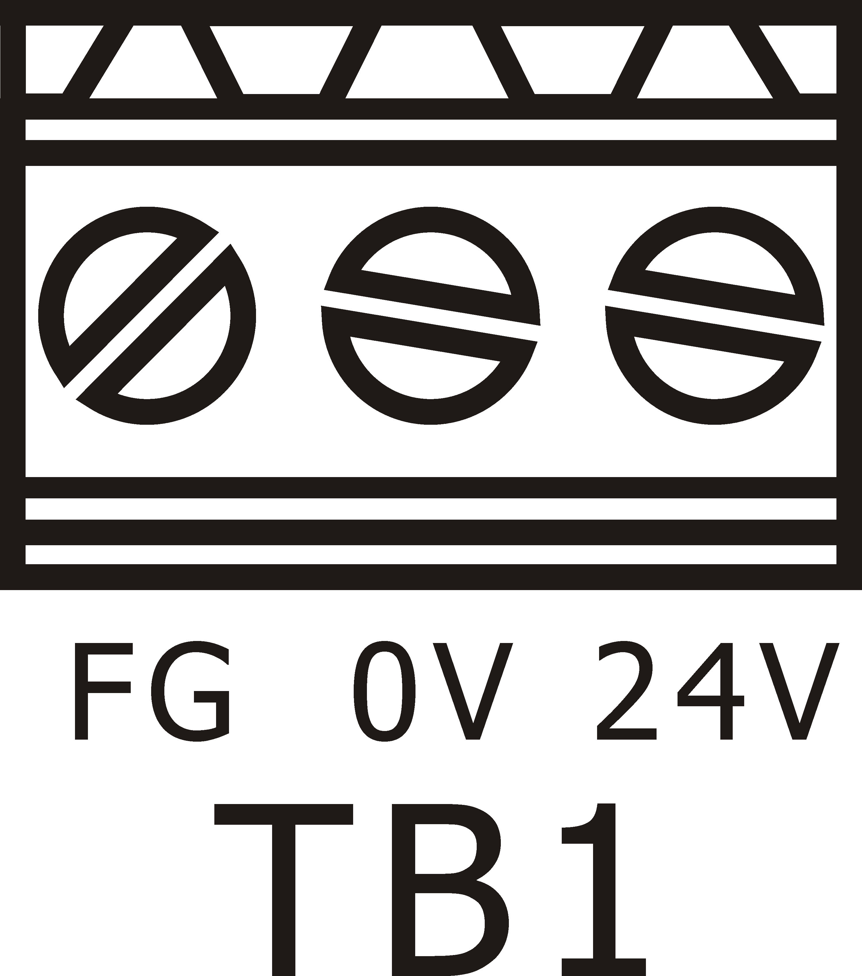
TB1 Placement Drawing
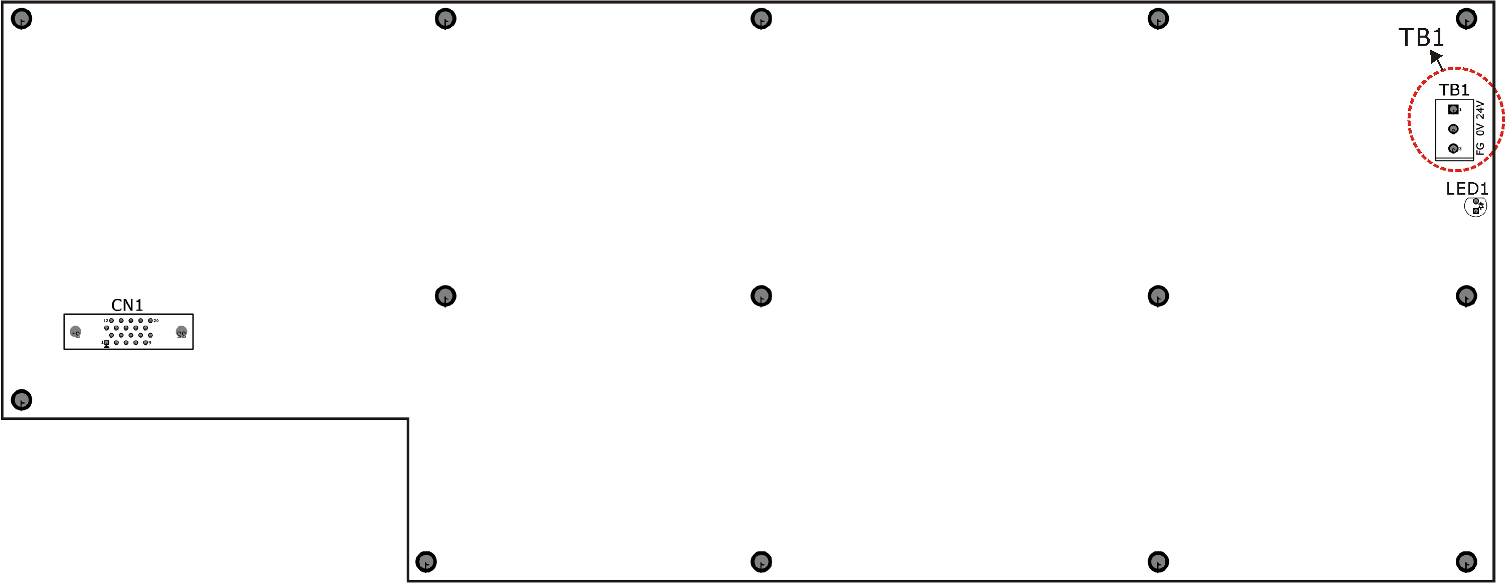
EtherCAT Connector
- CON1:EtherCAT cable IN
Connect upstream to the previous EtherCAT device.
- CON2:EtherCAT cable OUT
Connect downstream to the next EtherCAT device.
CON1 and CON2 Placement Drawing
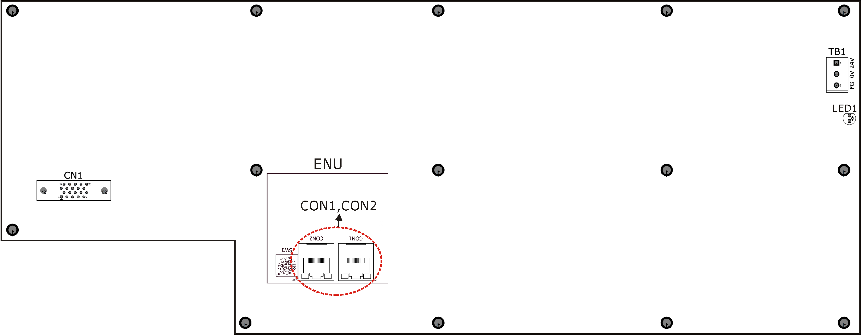
CN1: Handwheel connector
Handwheel connector CN1 uses 3M 20 PIN connector to link with external handwheel. This interface includes axial selection, multiply rate selection and handwheel counter feedback.
Pin |
Definition |
Explain |
1 |
X axis selection |
Input point |
2 |
Y axis selection |
Input point |
3 |
Z axis selection |
Input point |
4 |
A axis selection |
Input point |
5 |
B axis selection |
Input point |
6 |
C axis selection |
Input point |
7 |
A+ |
Hand wheel A+ signal input |
8 |
A- |
Hand wheel A- signal input |
9 |
B+ |
Hand wheel B+ signal input |
10 |
B- |
Hand wheel B- signal input |
11 |
NC |
Empty |
12 |
Handwheel indicator - |
Connect Handwheel LED Indicator - |
13 |
Multiply rate selection X1 |
Input point |
14 |
Multiply rate selection X10 |
Input point |
15 |
Multiply rate selection X100 |
Input point |
16 |
Multiply rate selection X1000 |
Input point |
17 |
Handwheel indicator+ |
Connect Handwheel LED Indicator + |
18 |
Common point of input signals |
Connect the Handwheel axial and rate selection COM Point |
19 |
5V |
Hand wheel power (Power: 1W) |
20 |
5G |
5V Power reference point |
CN1 Placement Drawing
Emergency Stop Button
The emergency stop button on the GMPU3 operator panel retains a normal close contact for external wiring use.
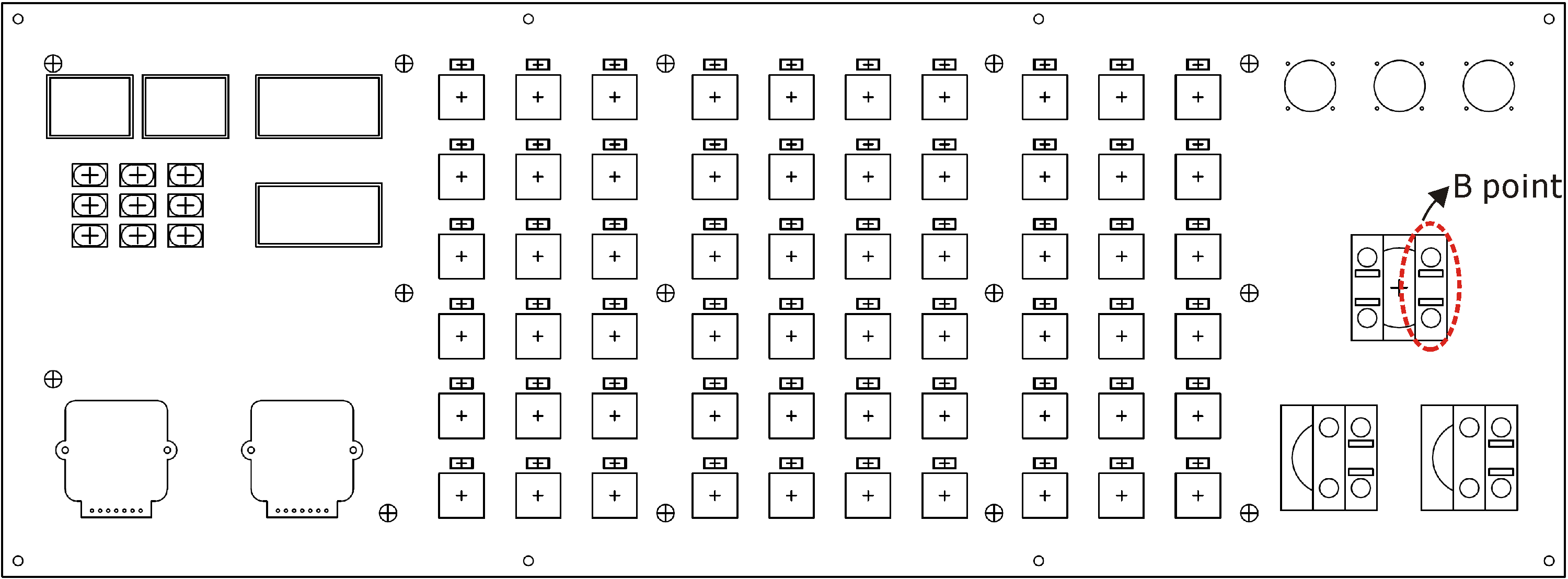
B point Placement Drawing