4.5.2 G01: Linear Interpolation
Linear Interpolation
Format:
- G01 X_Y_Z_A_F_ (M84)
- M86 Six axis any four axis, for example:
G01 X_Y_Z_A_F_
G01 X_Y_Z_B_F_
G01 X_Y_Z_C_F_
G01 X_Z_A_B_F_
- G01 X_Y_Z_A_B_C_F_ (M86R)
When the outline of the workpiece is a straight line, it is cut by the G01 command. M86R can move in the simultaneous axis (also can move in 5, 4, 2, 1 axis), M86 can move in any direction with 4 axes (also can be 3, 2, 1 axis with the simultaneous), M84 can be four-axis with the simultaneous (also 3,2,1 axis with the simultaneous), while the F_ value designated cutting feed rate, the speed can be feed rate override adjustment percentage Adjust it. Feed rate override adjustment is operated by the machine panel rotary switch.
The unit of F_ differs as defined by G94 (mm/min) or G95 (mm/rev). F_ is the continuous effective instruction, so the next single section cutting rate can be omitted when omitted. For example: F0.1 S3000 feedrate in G95 mode: 0.1 (mm/rev) x 3000 (rev/min) = 300 (mm/min)
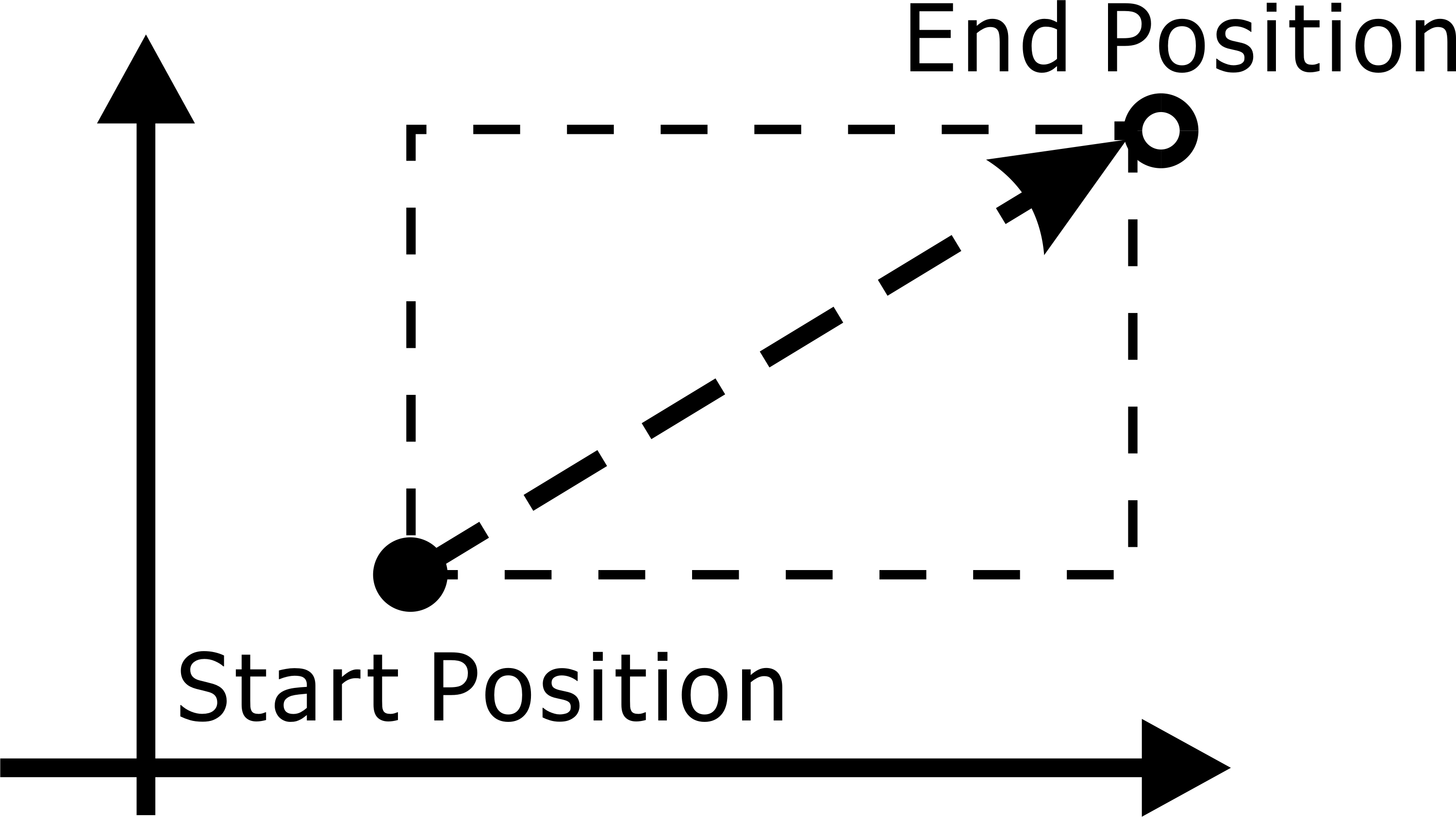
G01 2-axis Linear Interpolation
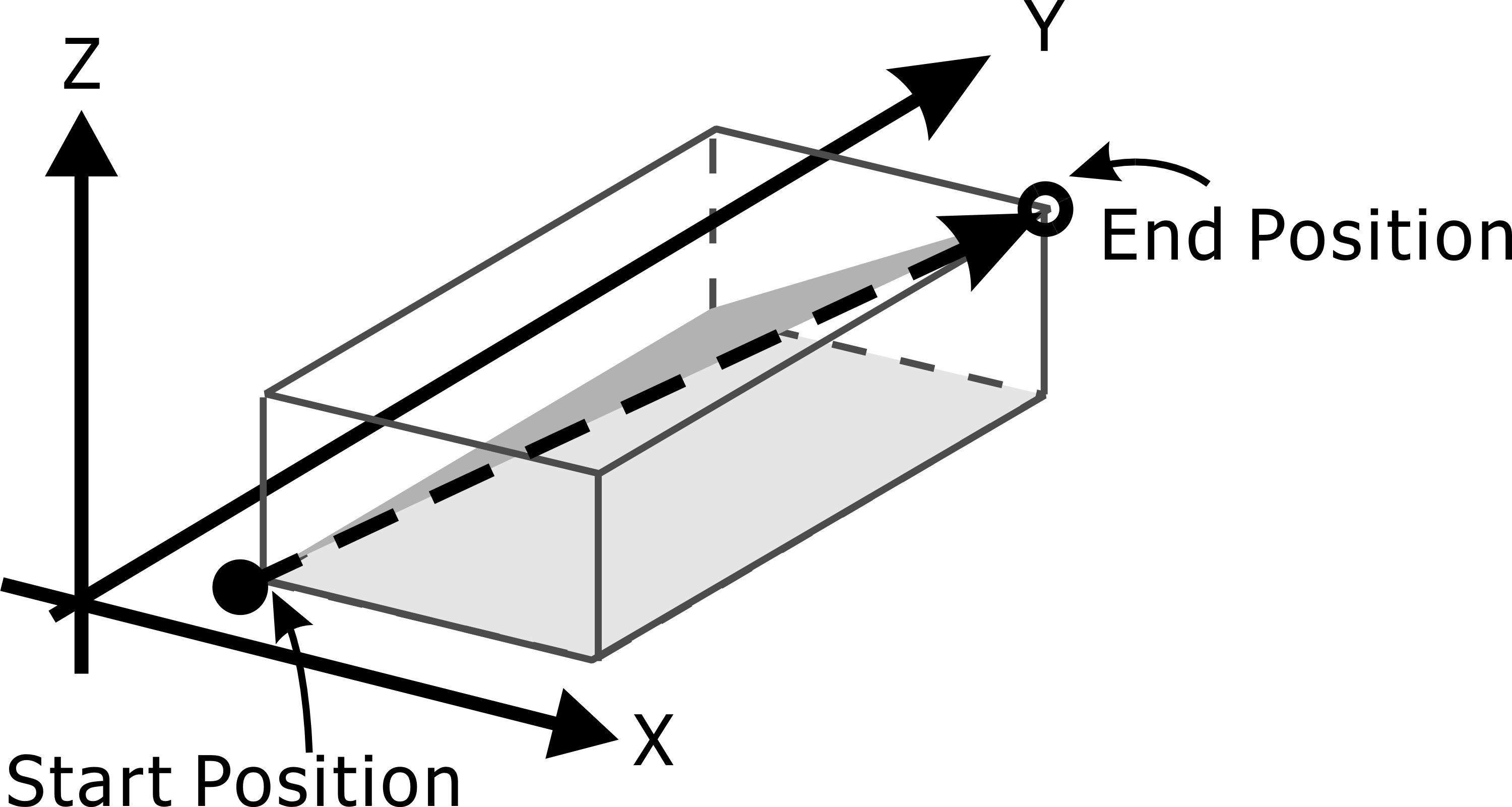
G01 3-axis Linear Interpolation
Note: |
That G01 is not related to the plane selection such as G17/G18/G19 for any two-axis linear interpolation. However, if the chamfering or rounding is required, the axis to be moved must be defined by G17/G18/G19 If the plane is the same, G17 must be G01 X_Y_L_F_ or G01 X_Y_R_F_, not G01 X_Z_F_. |
Linear Interpolation with Chamfered or Rounded Angle
Format:
G01 X_Y_L_F_
G01 X_Y_R_F_
Chamfering or rounding can only be performed in a specific plane, and both the chamfering or rounding of the line and the next line must be a linear interpolation command before chamfering or rounding is performed.
Chamfer is at a distance from the intersection of two straight lines L_ value of the distance, automatically add a chamfering instructions, so that the workpiece is not too chamfered angle. At the intersection of the two straight lines, the rounding automatically adds an arc command with a radius of R_, tangent to the arc with the two straight lines so that the chamfer of the original workpiece becomes a rounding.
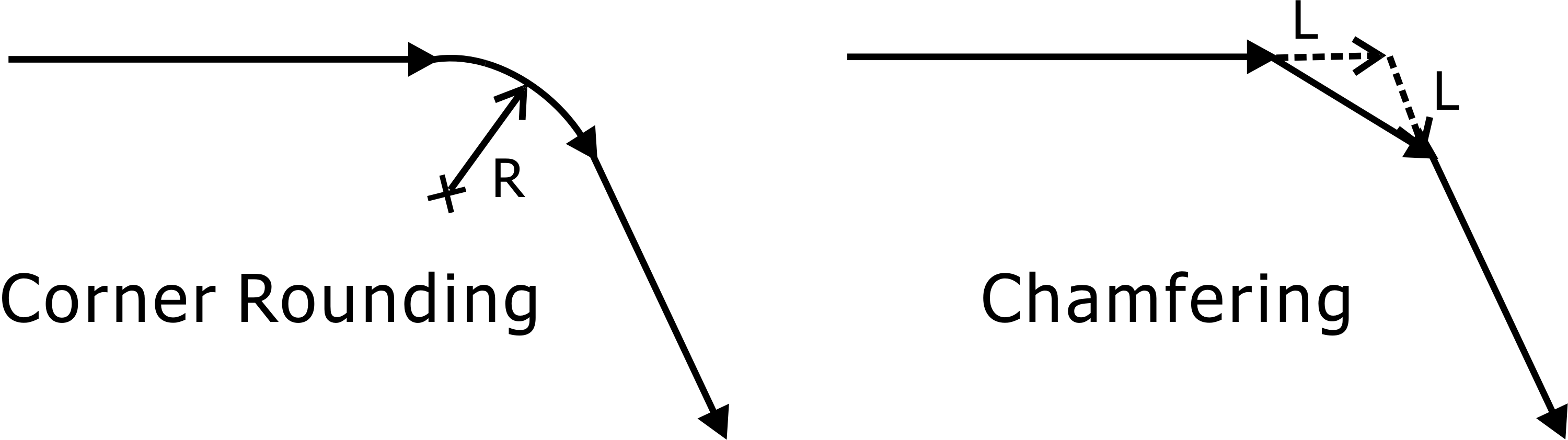
Corner Rounding and Chamfering
Note 1: |
The chamfer's L_ value or the R_ value of the rounding must be an appropriate size, which is not executable if the two values are too large. |
Note 2: |
The linear interpolation of round and chamfer is related to the plane selection. Only X_Y_L_ (R_) can be executed under G17. Only Y_Z_L_ (R_) can be executed under G19 and only X_Z_L_ (R_) can be executed under G18. |