4.6.3 G40/G41/G42: Tool Radius Compensation
Format:
G41 D_
G42 D_
G40
G41/G42 starts tool radius compensation and offsets the tool to the left/right of the starting point of the workpiece contour to be cut. Tool radius compensation left/right deviation judgement is based on the following definition: In the cutting path of the program, from the direction of cutting advance, the right cutter of the milling cutter is executed with G42 command; if the cutter is left offset, G41 command is used carried out.
When editing a program, only the tool number, such as D11, D12..., must be entered. The set D_ represents the tool number in the "parameter → tool compensation table", and the offset of tool radius compensation is the radius compensation value set by this tool number. This radius compensation value is the user's parameter before processing "parameter → tool compensation table" setting. For example: D12 indicates that the tool number is No. 12, and the radius compensation value No. 12 is 4.0, indicating that the cutter radius is 4.0 mm.
When executing the G41 or G42 command, the controller will use the radius value of the tool number specified by D_ as the compensation value. The D_ value is still memorized by the controller after being turned off until it is replaced by a new D_ value; if it is set to D00, it will be regarded as not making any tool radius compensation.
When performing tool radius compensation, the compensation state must be cancelled with G40 after the machining is completed, and the center point of the milling cutter should be returned to the actual coordinate point. In other words, when executing G40 command, the system will move in the opposite direction to the original left or right compensation value. When using G40, please make sure that the milling cutter is away from the workpiece to avoid damage.
In compensation mode, the system will perform tool radius compensation according to the following principles:
1. |
Corner path when the workpiece convex cutting: |
(1) |
When the included angle is less than 90 degrees: When the angle between the two path vectors is less than 90 degrees, the corner path of the workpiece convex surface has two modes of arc and intersection. This can be set in "Parameter → Attribute → Check Item → [ ] Arc corner for tool compensation". |
i. |
[ ] Arc corner for tool compensation: If this item is not selected, the CNC controller automatically calculates the intersection of these two paths. This intersection point becomes the starting point of the previous block and the starting point of the back block. |
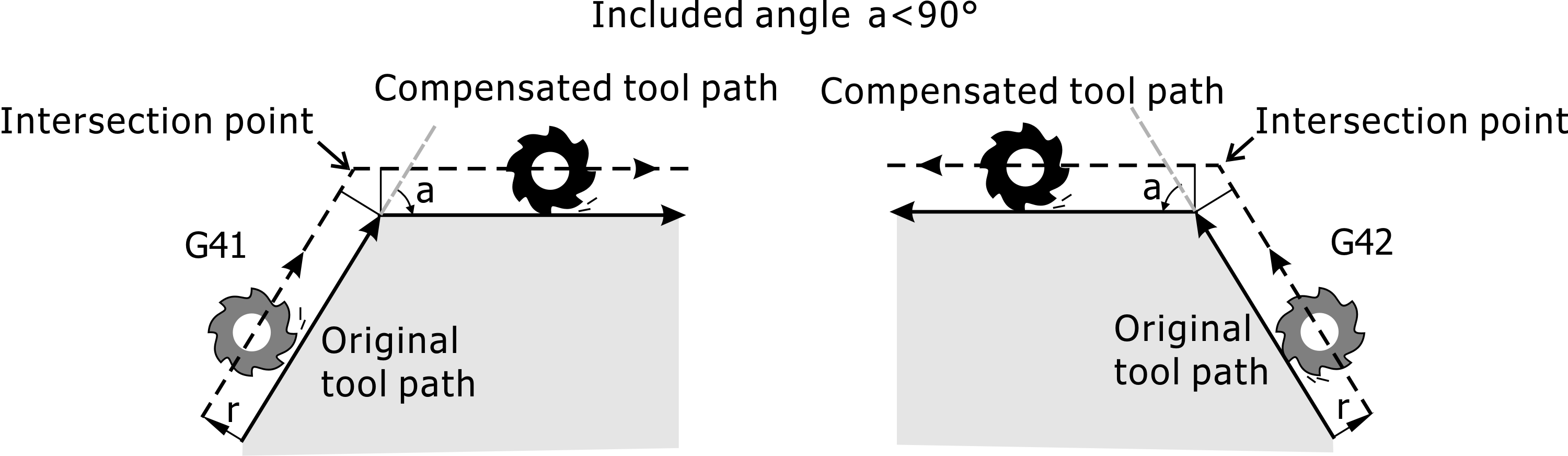
Intersetcion Point of Tool Paths with an Included Angle Less Than 90 Degrees
ii. |
[√] Arc corner for tool compensation: However, if this item is selected, all corner paths are processed by circular arcs. |
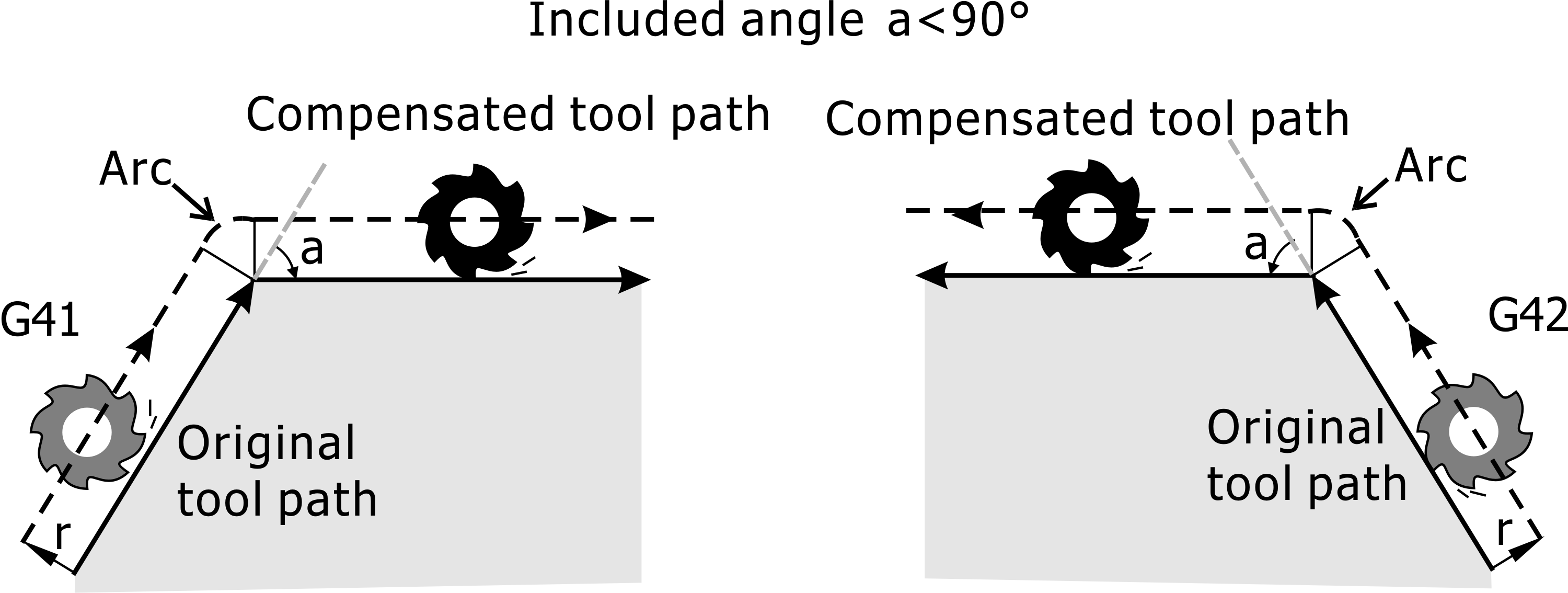
Arc Corner of Tool Paths with an Included Angle Less Than 90 Degrees
(2) |
When the included angle is greater than 90 degrees: When the angle between the two path vectors is greater than 90 degrees, the corner path of the workpiece convex surface is treated with an arc. |
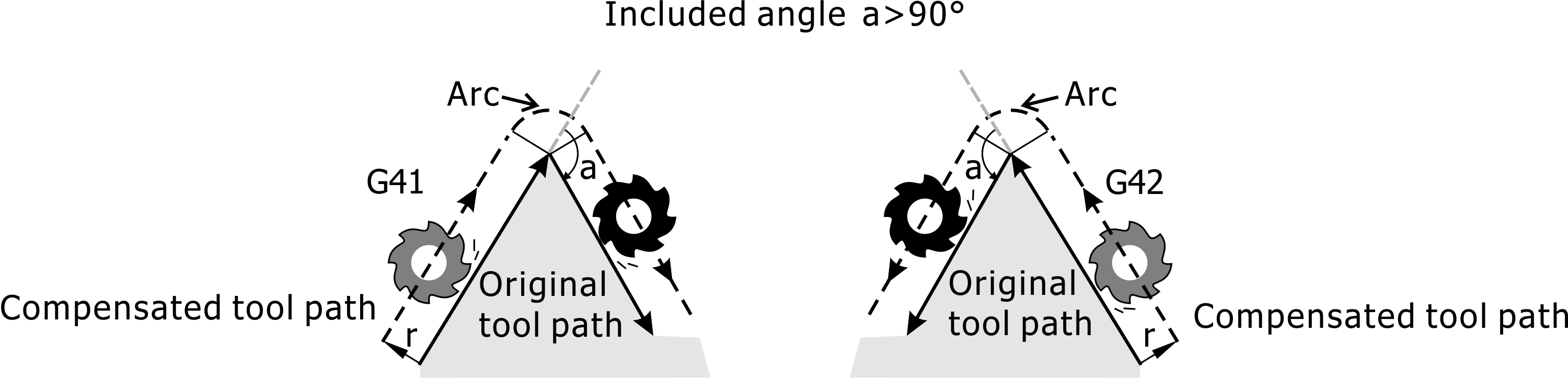
Arc Corner of Tool Paths with an Included Angle Greater Than 90 Degrees
2. |
Path at concave: system auto calculates two path intersection, and this intersection became pre block end position and start position of back block. |
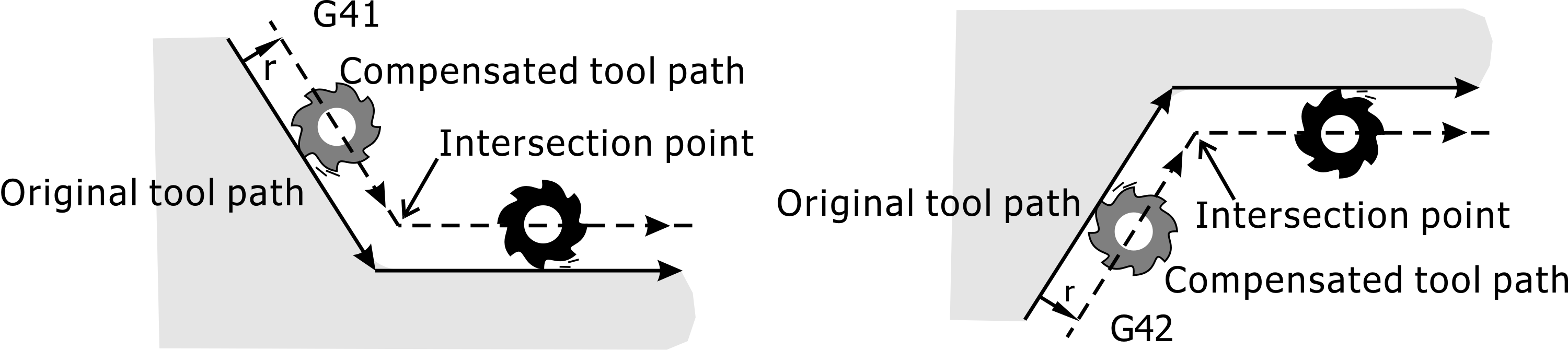
Intersetcion Point of Tool Paths When Cutting the Concave Side of Workpiece
Note 1: |
The compensation train in block only allow to use linear interpolate command (G00/G01), otherwise if arc interpolate command (G02/G03) used will alarm and stop. |
Note 2: |
To change tool radius, or to toggle G41, G42 mode in tool compensation were not allow. |