5.3.4.1 Settings of Rotary Order and Rotary Mode
There are 4 types of rotation modes:
0 |
: |
No rotation, no effect. |
1 |
: |
The rotation order instruction makes three rotations from the angle value specified by the A_B_C_ value. |
2 |
: |
The new coordinate system is specified by the direct angle. |
3 |
: |
The new coordinate system is specified by the normal vector. |
4 |
: |
The new coordinate system is specified by the projection angle. |
- Rotary mode 1: Three rotations are made from the angle value specified by the A_B_C_ value.
This rotation mode specifies three rotations in sequence, and the rotation in the latter order is based on the last rotation of the coordinate system. Each rotation can rotate around the X axis or the Y axis or the Z axis, so there may be 81 rotations, but based on the Euler rotation theorem, the rotation axis does not repeat to define any rotation, so there are 12 rotations available Define any rotation.
The three rotations are specified by the rotation order, A is first, B is second, and C is third. The rotation order is a two-digit decimal number. After converting to a two-digit number, each two-digit number specifies a rotation method.
XX XX XX
#3 #2 #1
Each group of 2 digits XX:
00 Do not rotate
01 Rotate around the X axis
10 Rotate around the Y axis
11 Rotate around the Z axis
#1 The first rotation, specified by the A_ value.
#2 The second rotation, specified by the B_ value.
#3 The third rotation, specified by the C_ value.
Example:
First round the X axis and then around the Y axis, and then round the Z axis to 2 digits. 11 10 01 = Decimal 57
First around the Z axis and then around the Y axis and then around the X axis in binary 2 01 10 11 = Decimal 27
First around the X axis and then around the Z axis and then around the Y axis as a binary digit 10 11 01 = Decimal 45
First around the Y axis and then around the Z axis and then around the X axis to binary 1 01 11 10 = Decimal 30
First around the Z axis and then around the Y axis and then around the Z axis to binary 2 11 10 11 = Decimal 59
First around the Z axis and then around the X axis and then around the Z axis to binary 2 11 01 11 = 10 Decimal 55
Example of calculation description: Take the previous example of winding the X axis and then the Y axis and then the Z axis. For example, the A_B_C_ value is 11 10 01,thus:
1 1 1 0 0 1
32 16 8 4 2 1
The numerical calculation is (32ϒƒ1)+(16ϒƒ1)+(8ϒƒ1)+(4ϒƒ0)+(2ϒƒ0)+(1ϒƒ1)= 57
The second rotation is the rotation based on the first rotated coordinate system, and the third rotation is also the rotation based on the second.
For example: G158 L1 P10157 X2. Y0. Z10. A20 B20 C-30 U0 V10 W0 specifies the new coordinate system to be translated first X2 Y0 Z10, then rotate 20 degrees around the X axis, then rotate around the Y axis by 20 degrees, and then rotate around the Z axis. Rotate -30 degrees, and then translate the U, V, W specified by U, V, W in the rotated coordinate system again to 0, Y direction 10, and Z direction 0.
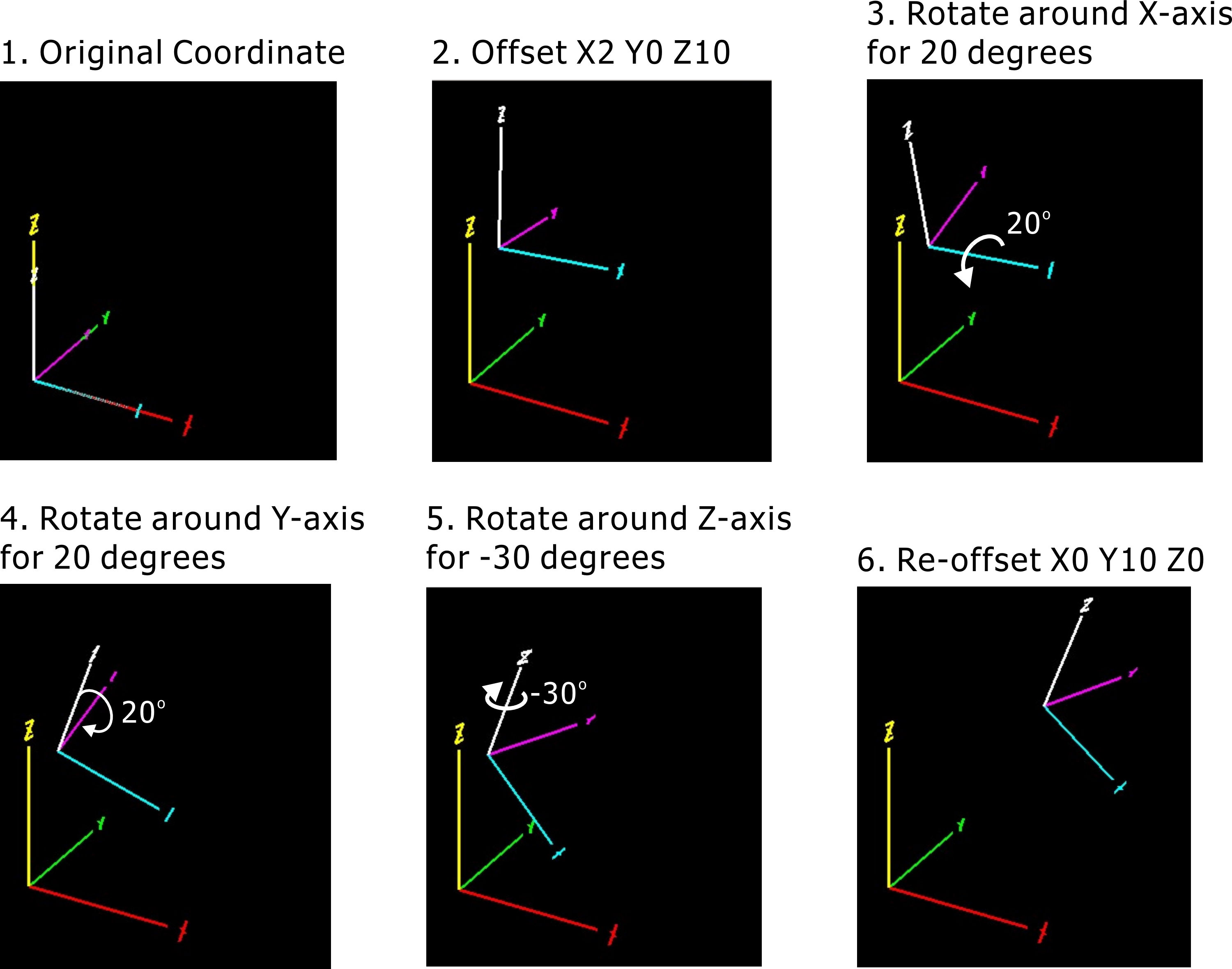
Rotary Mode 1
- Rotation mode 2: direct angle specification.
The angle of the motion axis is directly specified by the A_B_C_ value. If it is the AC axis mechanism, it is specified by the A_ value and the C_ value. If it is the BC axis mechanism, it is specified by the B_ value and the C_ value. Normally, in this mode, the rotary axis will be selected to be actuated. After the operation, the main axis is perpendicular to the XY plane of the new coordinate system. If you need to rotate the XY plane again, you need to add one more line of instructions. Examples are as follows:
G158 L3 P10200 X0 Y0 Z10 A0 B20 C45 U0 V0 W0
G158 L3 P01159 X0 Y0 Z0 A0 B0 C10 U0 V0 W0
;Increment and then turn the XY plane to 10 degrees
- Rotation mode 3: Normal vector designation.
A vector is formed by the A_B_C_ value. This vector is the direction of the tool. It is also the normal vector of the new coordinate system. If this coordinate system needs to do another XY plane rotation, you can refer to the example of the direct angle specification for rotation.
- Rotation mode 4: Projection angle designation.
The A_ value specifies the projection angle formed by the XY plane and the positive X axis of the new coordinate system. The B_ value specifies the projection angle formed by the new XY plane and the Y axis. At this time, the X axis of the new coordinate system falls on the XZ plane of the original coordinate system. Upper (plane with y = 0), where C_ value specifies the angle at which the last new XY plane is rotated. Examples are as follows:
Example 1:
G158 P10400 X0 Y0 Z0. A20. B30. C0 U0 V0 W0
Example 2:
G158 P10400 X0 Y0 Z0 A20. B30. C15. U0 V0 W0
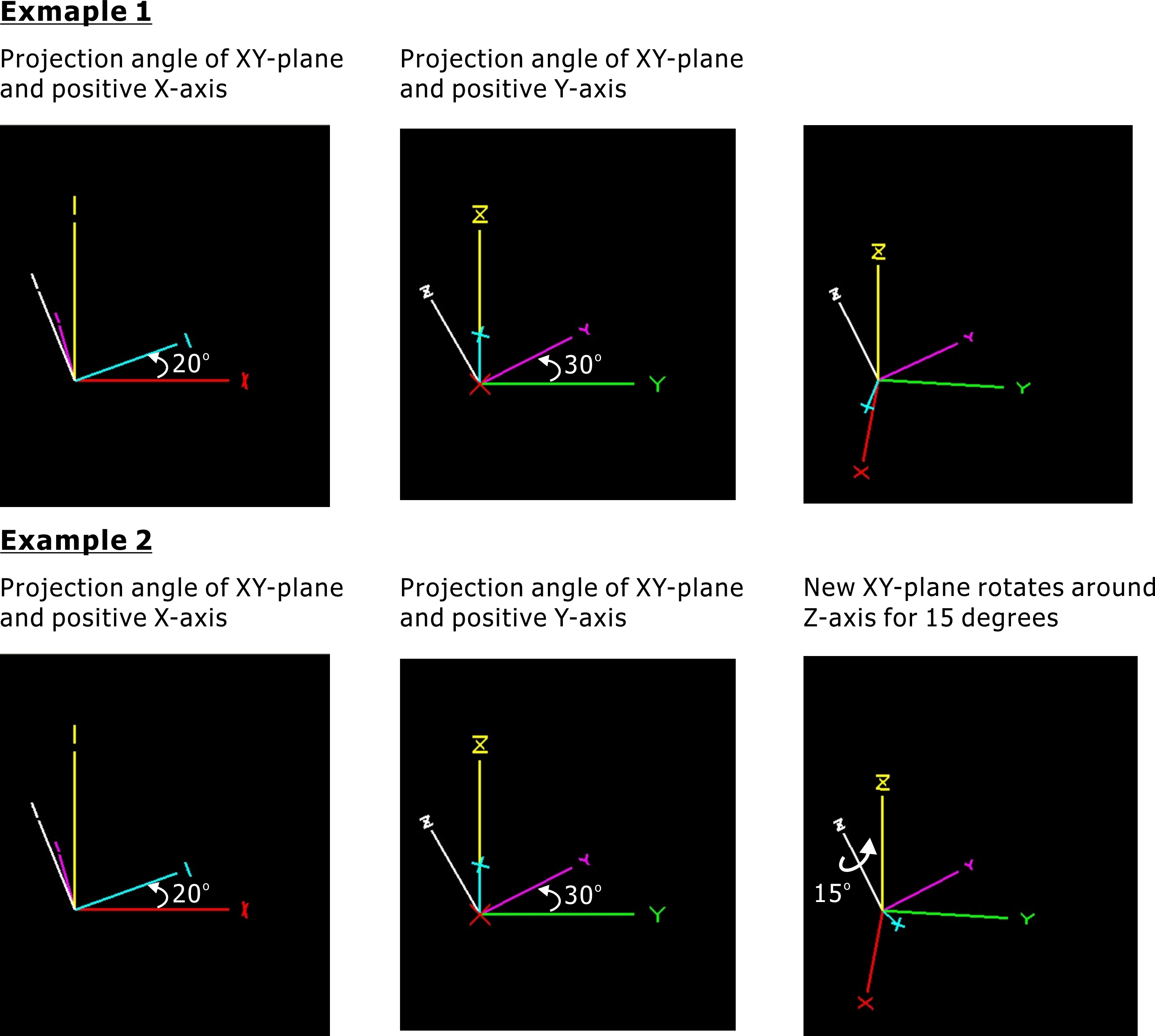
Rotary Mode 4