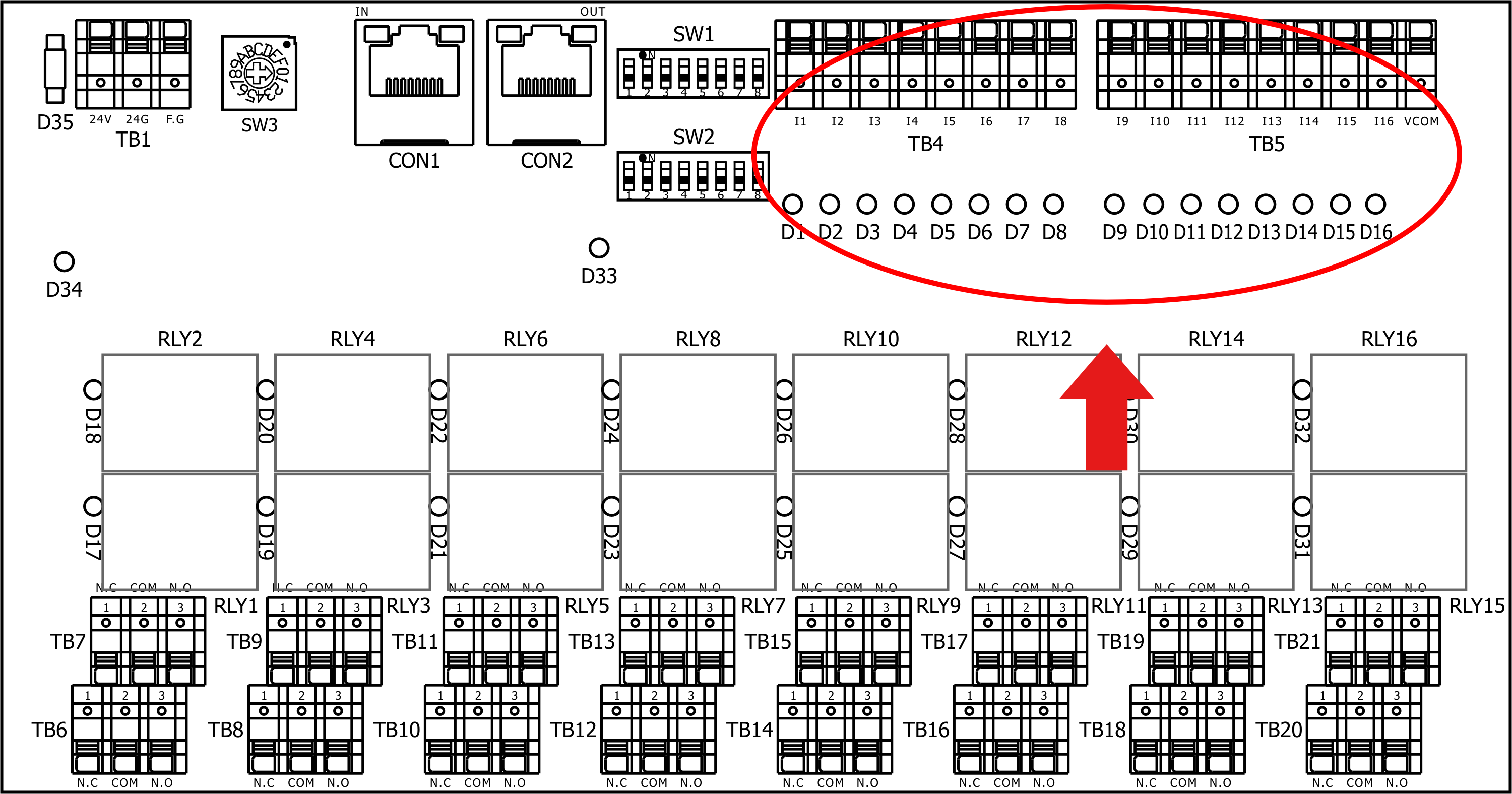
2.5.2 TB4, TB5: Input Terminal
TB4 and TB5 are digital isolated signal input terminals. There are sixteen inputs and one common input. The 16 input points can be connected via PNP connection method (commonly connect to DC 24G, input point turn on by DC 24V) or via NPN connection method (commonly connect to DC 24V, input to turn on) each input point is allocated a LED indicator (when the input point is turn on the LED indicator, would light up)
Please be aware: You can only choose to use NPN or PNP method to connect the 16 input signals, you cannot use both the NPN and PNP connection method and the common point of the input signal (VCOM) cannot use the same power supplier to the EQU unit power terminal (TB1) or it would cause the isolation design of the input point to lost its function.
TB4 input terminal input points |
I1 |
I2 |
I3 |
I4 |
I5 |
I6 |
I7 |
I8 |
VCOM |
Its retrospective LED light |
D1 |
D2 |
D3 |
D4 |
D5 |
D6 |
D7 |
D8 |
None |
TB5 input terminal input points |
I9 |
I10 |
I11 |
I12 |
I13 |
I14 |
I15 |
I16 |
VCOM |
Its retrospective LED light |
D9 |
D10 |
D11 |
D12 |
D13 |
D14 |
D15 |
D16 |
None |

TB4, TB5 Input Terminals

TB4, TB5 Placement Drawing