3.6 Main Spindle
Selecting "Spindle" will open the menu as follows:
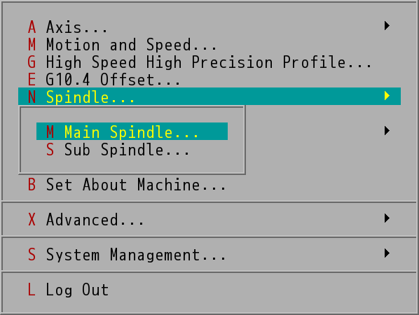
Spindle Selection Menu (Only M86/M86R Has Sub Spindle)
Choose "Spindle" will open this menu, choose "Main Spindle" or "Sub Spindle", after choosing this option to set the main spindle or sub spindle, the following menu would appear, to provide machine manufacture settings for the spindle relevant parameter.
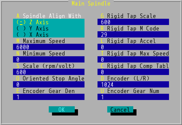
"Main Spindle" Dialog Box
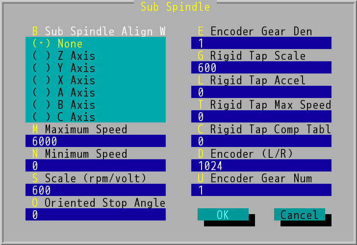
"Sub Spindle" Dialog Box
- Spindle (Sub Spindle) Align With: Choose spindle align with axis, tool length correction value will use it for value setting. Spindle usually is place upon Z axis, but sometime, due to special need, it can be place on other axis, during this time, you need to go into the dialog box choose "Spindle Align With → ( ⋅ ) X Axis/Y Axis/Z Axis" option, please use the direction key to make your choice.
- Maximum Speed: Unit pre-set as rpm to set the spindle Maximum Speed.
- Minimum Speed: unit pre-set as rpm to set the spindle Minimum Speed.
- Scale: Unit as rpm/volt use to set axis voltage order ratio. INCON-M84/M86/M86R will according to PLC manage and send out DC 0 V~+10 V or DC 0 V~-10 V to spindle driver. This item setting to inform INCON-M84/M86/M86R per voltage of voltage let spindle know how many rpm to spin.
- Oriented Stop Angle: While drilling, sometime the spindle will stop at a specific angle, this item is for definition of specific angle, input value 0-359.
The next few items are parameters related rigid tapping. Before processing rigid tapping, please make sure the spindle is equipped with the encoder and spindle drive.
- Encoder Gear Den (Denominator): When the spindle pass through gear ratio coupling, the value of the gear at the side of the encoder compare to the gear at the side of the spindle value must be 1, 2, 4, 8, 16, 32 (square of 2). The value is the gear number to the denominator the numerator must be one for example, 1/1、1/2、1/4、1/8 ….
- Rigid Tap Scale: Setting spindle voltage ratio rpm/volt for rigid tapping. When conducting rigid tapping it usually require the spindle to lower its spinning speed and with larger torque. When the spindle driver through spindle mode change to tapping mode, the voltage corresponding spinning speed of the spindle will be different from the spindle mode.
- Rigid Tap M Code: set the initiate tapping special use M code, usually is M29, it can also according to need, change to other code, but cannot be system set function M00/M01/M02/M30 or M95/M97/M98/M99 or M03/M04/M05/M06 and another M code.
- Rigid Tap Accel: The acceleration of spindle setting, during rigid tapping mode require PLC been used in partnership.
- Rigid Tap Max Speed: Pre-set value is 0, meaning rigid tapping function cannot be used yet. When machine has rigid tapping equipment, according to the nature of the machine, set the appropriate tapping max rpm, can initiate the rigid tapping function. Base on this limit the max value of S code (tapping speed) order the tapping cycle prior to tapping, as usage preparation. Thus, limit S code to max value, if surpassing this value, this value will replace it.
- Rigid Tap Comp Table: This parameter definition is the PLC long data start number of taping compensation table. Because most spindle driver have acceleration and deceleration nature, thus, could lead the tapping to be too deep. Please first use 100 rpm and conduct one tapping per 100 rpm and record the depth of each tapping. Then according to the formula, calculate the compensation value of tapping at each, different speed. Fill the first rpm compensation data in the PLC long data that start number defines by this item, then follow compensation data for following PLC long data.
Tapping compensation formula is as following:
Compensation value = 4096 × Overcut depth / Pitch
For example, Pitch = 0.5mm, the programmed tapping depth = 100mm; the calculated actual tapping depth and compensation values are listed below:
Rigid Tapping Speed |
Actual Tapping Depth |
Programmed Tapping Depth |
Overcut Depth |
Calculated Compensation Value |
100 rpm |
101.5 mm |
100 mm |
1.5 mm |
4096×1.5/0.5 =12288 |
200 rpm |
103.0 mm |
100 mm |
3.0 mm |
4096×3.0/0.5=24576 |
300 rpm |
104.5 mm |
100 mm |
4.5 mm |
4096×4.5/0.5=36864 |
400 rpm |
106.0 mm |
100 mm |
6.0 mm |
4096×6.0/0.5=49152 |
500 rpm |
108.0 mm |
100 mm |
8.0 mm |
4096×8.0/0.5=65536 |
If we at here set rigid tapping compensation to initiate 100 numbering, the PLC number according to number 100, the following is to make the compensation value according to the table above, from 100 to start enter, into PLC long data according to the table above.
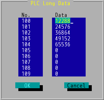
Fill rigid tapping compensation data to "PLC Long Data"
If the spindle got rigid tapping mode and use the CNC controller spindle to acceleration and deceleration, and this parameter is too deep compensation value, for example: if the max tapping rpm is 3000 rpm, you can use 1500 rpm to test too deep. Calculate the compensation value will directly fill this item.
- Encoder (unit: line/round): Set spindle encoder resolution must be 1024 or 2n value, for example 256, 512 as working properly.
- Encoder Gear Num (Encoder Gear Numerator) : set the spindle spinning encoder to the numerator of the spindle gear ratio.