7.3.1 Zero Point at Negative Direction
Purpose: When zero point at negative direction, the laser measurement of backlash and pitch error's setting.
If for example X axis zero point at negative direction, the distance is larger then 1000 mm, can be split into 40 sectors, each sector length (screw pitch error compensation distance) 25 mm, each move would stop for 3 seconds, provide laser measurement time. While conducting compensation to the two terminals of the distance, there are over 2 mm distance that can be used to cancel backlash.
INCON-M84/M86/M86R with laser measurement of backlash and pitch error example:
; (Zero Point at negative direction), please do manual homing first
; Sector Length= 25 mm, 40 sectors. (The traverse is larger than 1000 mm)
; at each side terminal has 2 mm for eliminate backlash
;
; Main program
G90 G28 X0 ; return to machine zero point
G91 G1 X-2. F2000 ; move backward -2 mm for eliminate backlash
G4 P1
G1 X2.
M97 P0001 L40 ; call subroutine 40 times
G91 G1 X2. ; move backward 2 mm for eliminate backlash
G4 P1
G1 X-2.
M97 P0002 L40 ; call subroutine 40 times
M30
;
; First, four types of value combine to use movement sub program
O0001
G91 G1 X25. ; move forward 25 mm
G4 P3. ; every sector dwell 3 seconds
M99
;
O0002
G91 G1 X-25. ; move backward -25 mm
G4 P3 ; every sector dwell 3 second
M99
When laser measure and system are both ready, afterwards we can start at measurement to receive similar to below curve, auto calculation average backlash value is containing within.
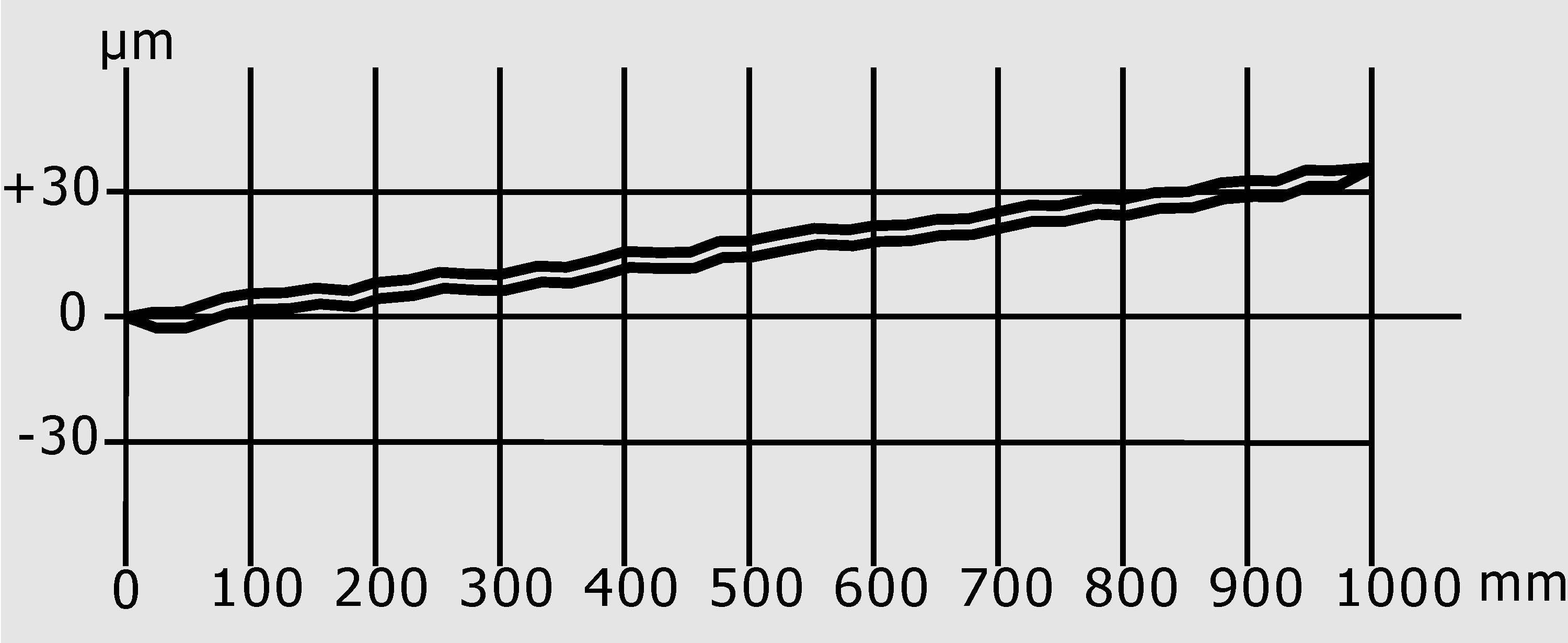
Laser Detection Error Diagram (Not Setting Pitch Error Compensation and Backlash)
Note: |
If the two-curve line is not the same or cross with each other, it means the machine got problem. Must first adjust machine, then reset machine measurement, until the two lines are the same. |
After getting correct info, put backlash value into machine parameter, this axis parameter backlash column. Then, redo auto measurement, here, the two lines should cover each other, if they still don't cover each other, must adjust the system again, then reset the system, till the two lines cover each other.
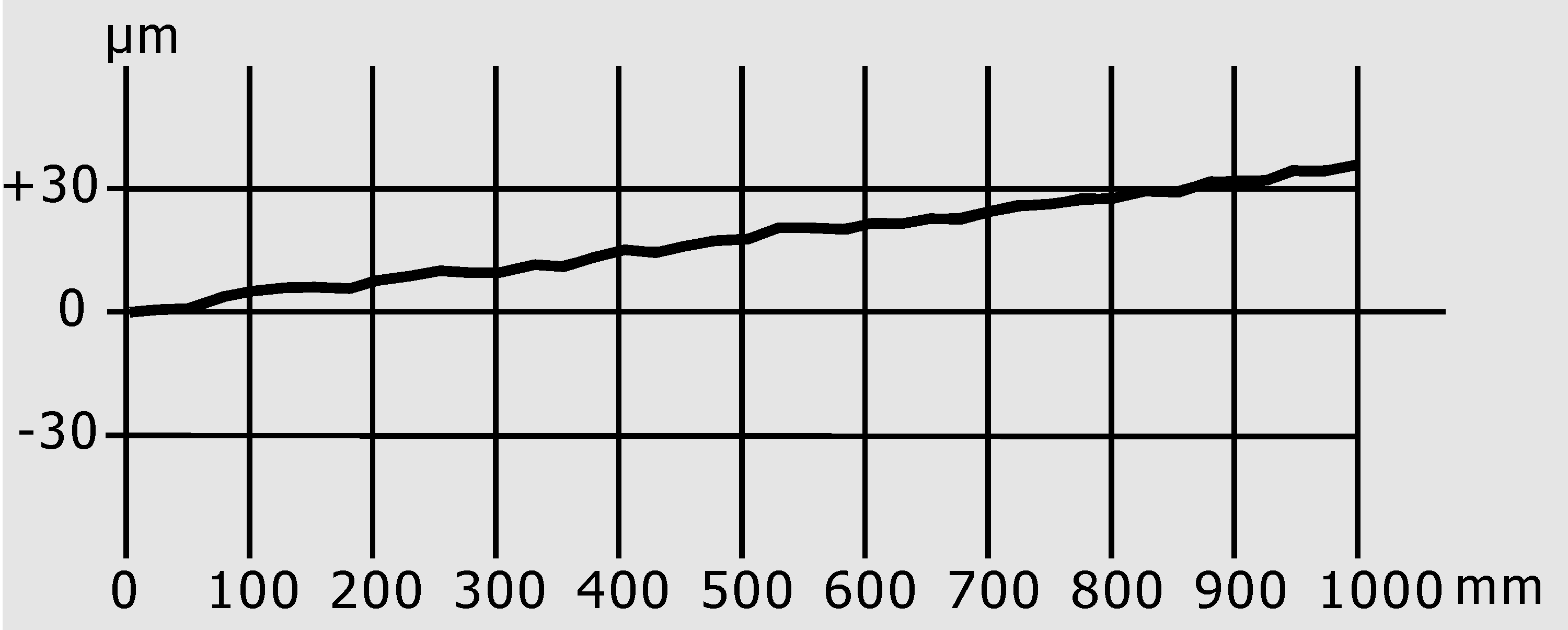
Laser Detection Error Diagram (Only Backlash Is Set)
When conducting leaser measurement, it would show laser measurement vale and each error value with screw. The pitch error value should according to the below calculation receive compensation: (positive and negative value could exist)
Laser measurement position – Machine position on controller = Pitch error compensation value
If laser error count did not match result of above equation, check laser instrument sign setting again.
Pitch error compensation accepts absolute compensation data or incremental compensation data. If wish to set Incremental compensation value, then set INCON-M84/M86/M86R machine parameter "Motion and Speed→Check Item→INC Pitch Comp" to be selected.
Take the first and the fourth combination of the installation method of the laser detector and the mirror surface and the zero-position setting as an example (home at negative), measure the positive value, the compensation value as below:
No. |
CNC Controller Machine Position |
Laser Detection Measured Position |
Absolute Error Compensation Value |
Incremental Error Compensation Value |
0 |
0 (Zero Point) |
0 |
0 |
0 |
1 |
25.000 |
25.001 |
1 |
1 |
2 |
50.000 |
50.002 |
2 |
1 |
3 |
75.000 |
75.005 |
5 |
3 |
4 |
100.000 |
100.007 |
7 |
2 |
.. |
...... |
...... |
.. |
.. |
39 |
975.000 |
975.033 |
33 |
.. |
40 |
1000.000 |
1000.035 |
35 |
2 |
41 |
.. |
.. |
0 |
0 |
When filling in machine parameter for the axis's screw pitch error compensation table, you must first fill in home position (within the example it is 0), then put the error compensation value of each behind (within 0 it must fill in 0).
1. Use absolute error compensation value, fill in as following:
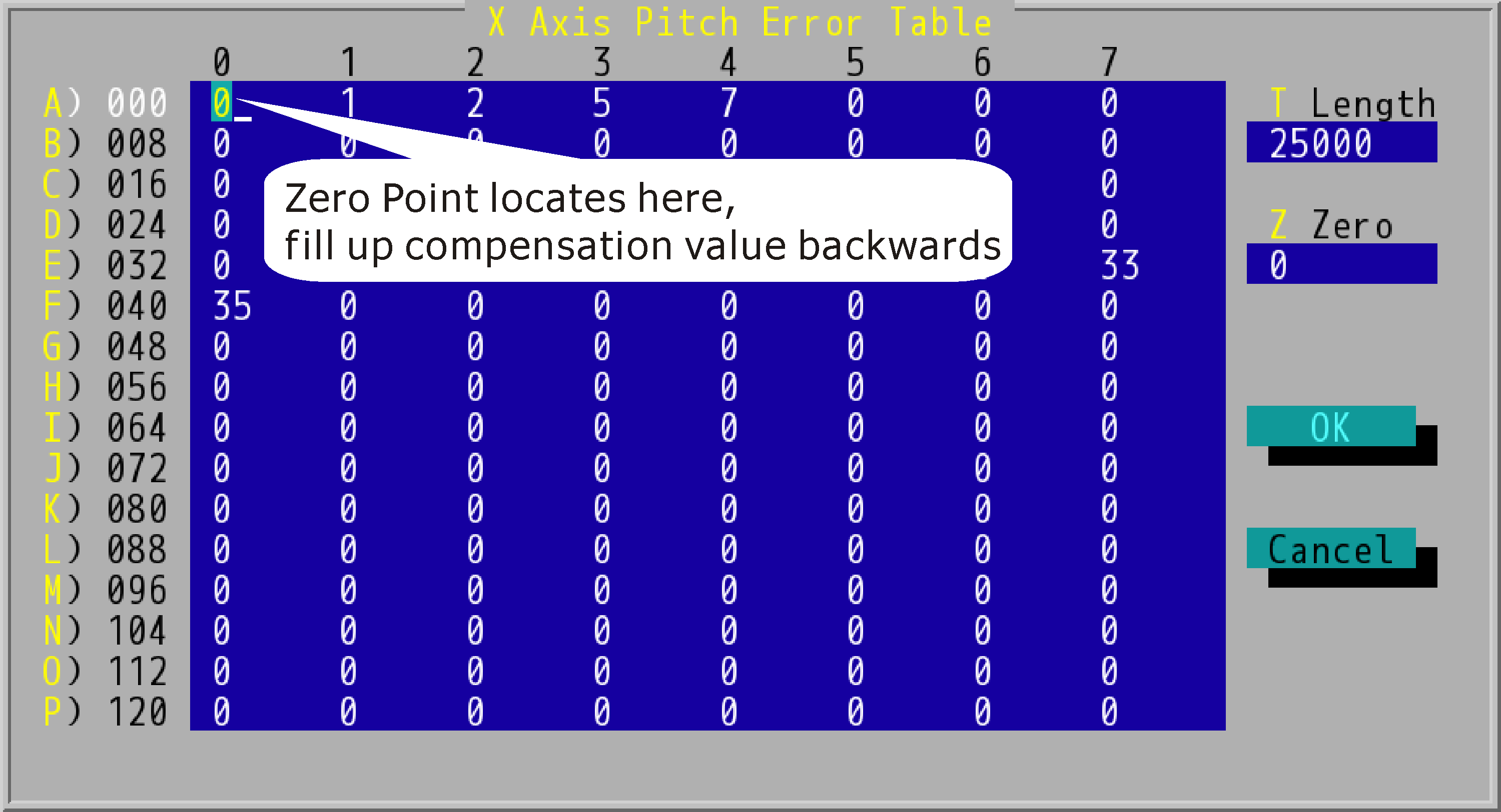
"X Axis Pitch Error Table" Setting (User Absolute Error Compensation, Zero Point at Negative Direction)
2. Use increment error compensation table filling as below:

"X Axis Pitch Error Table" Setting (User Increment Error Compensation, Zero Point at Negative Direction)
Run program again after fill up pitch error compensation table, can get two curves overlap and almost level.
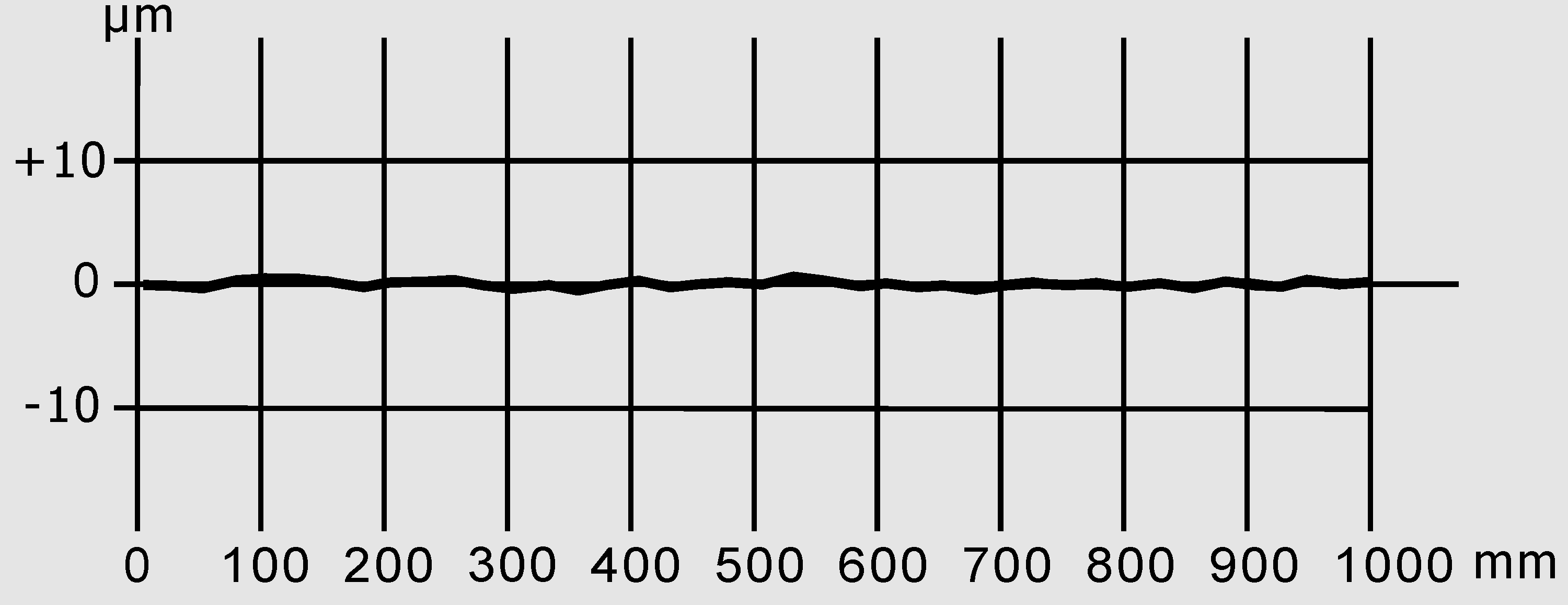
Laser Detection Error Diagram (Backlash and Pitch Error Both Set)