7.3.2 Zero Point at Positive Direction
Purpose: When zero point at positive direction, the laser measurement of backlash and pitch error's setting.
Use laser measurement and reflection glass to setting method and home setting, form a second and third type of combination.
Assuming if Y axis home is at positive, travel distance is larger than 600 mm, it can be split into 30 sectors, each sector (screw pitch error compensation distance) 20 mm, each movement will stop for 3 seconds, to provide laser measurement time. Then within compensation distance's two terminals, it has over 2 mm space travel cancel backlash, the composition is as following:
INCON-M84/M86/M86R with laser measurement of backlash and pitch error example:
;
; (Zero Point at positive direction), please do manual homing first
; Sector Length= 20 mm, 30 sectors. (The traverse is larger than 600 mm)
; at each side terminal has 2 mm for eliminate backlash
;
; Main program
G90 G28 Y0 ; return to machine zero point
G91 G1 Y2. F2000 ; move backward -2 mm for eliminate backlash
G4 P1
G1 Y-2.
M97 P0001 L30 ; call subroutine 30 times
G91 G1 Y-2. ; move backward 2 mm for eliminate backlash
G4 P1
G1 Y2.
M97 P0002 L30 ; call subroutine 30 times
M30
;
; First, four types of value combine to use movement vice program
O0001
G91 G1 Y-20. ; move backward -20 mm
G4 P3 ; every sector dwell 3 seconds
M99
;
O0002
G91 G1 Y20. ; move forward 20 mm
G4 P3 ; every sector dwell 3 seconds
M99
Because zero point at positive direction, measurement value should be negative, such value should be as following:
No. |
CNC Controller Machine Position |
Laser Detection Measured Position |
Absolute Error Compensation Value |
Incremental Error Compensation Value |
0 |
0 (Zero Point) |
0 |
0 |
0 |
1 |
-20.000 |
-20.002 |
-2 |
-2 |
2 |
-40.000 |
-40.005 |
-5 |
-3 |
3 |
-60.000 |
-60.004 |
-4 |
1 |
4 |
-80.000 |
-80.007 |
-7 |
-3 |
.. |
...... |
...... |
...... |
...... |
29 |
-580.000 |
-580.015 |
-15 |
.. |
30 |
-600.000 |
-600.013 |
-13 |
2 |
31 |
.. |
.. |
0 |
0 |
When filling in pitch compensation table, must first fill in home position (in this example it is 30) then place in the compensation value from 30 moves forward (The 30's need fill in 0).
1. Use absolute error compensation value, fill in as following:

"Y Axis Pitch Error Table" Setting (User Absolute Error Compensation, Zero Point at Positive Direction)
2. Use increment error compensation table filling as below:
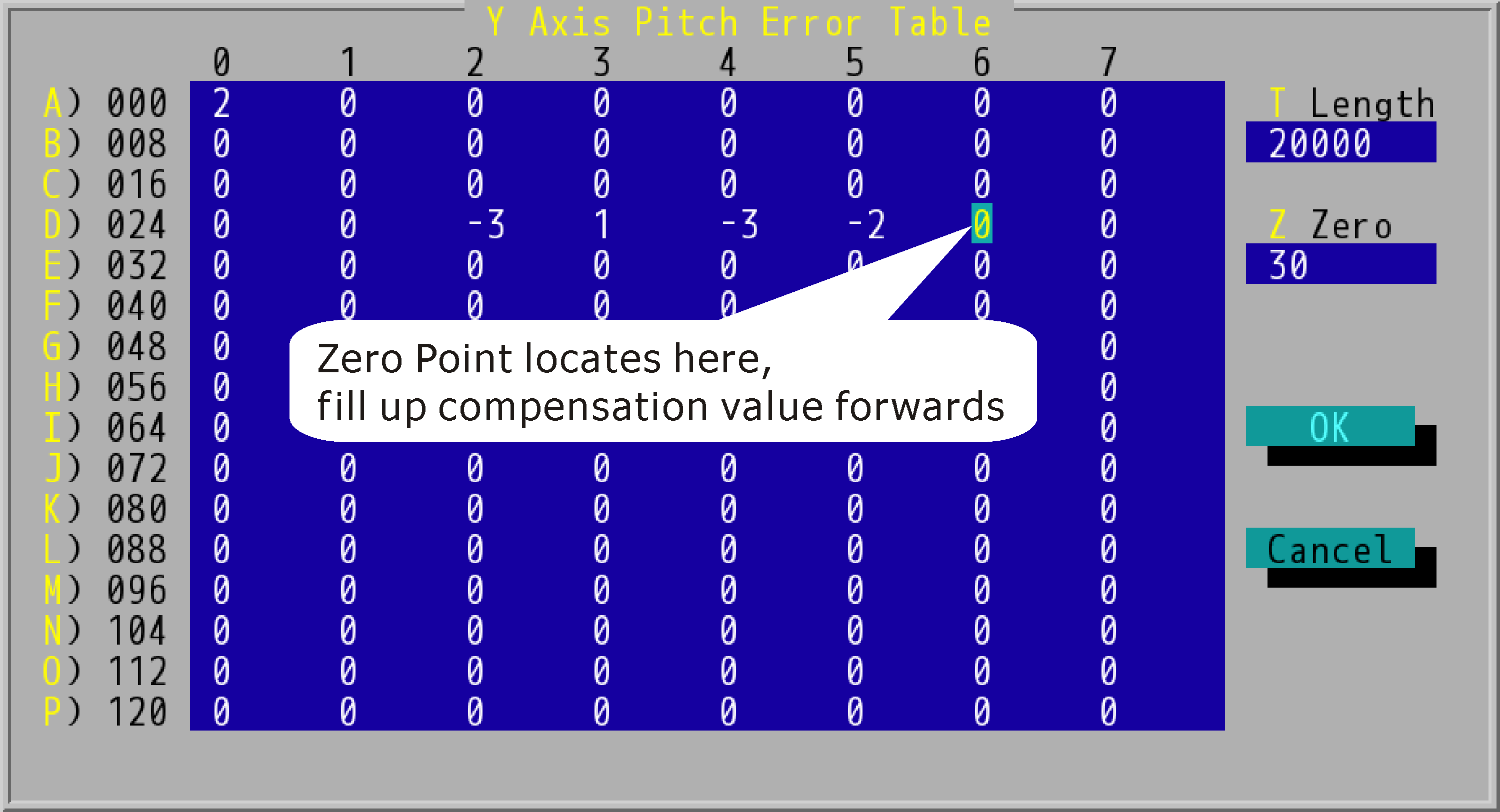
"Y Axis Pitch Error Table" Setting (User Increment Error Compensation, Zero Point at Positive Direction)
Same, after the axis and pitch error compensation has been filled out, redo laser measurement, you should get the two lines to cover each other and level closely.
If home is not set at one of the two terminals, but is set in middle. Then, it need to split into positive traverse and negative traverse two sector, if separated we need to conduct positive traverse and negative traverse two laser measurement for pitch error compensation. Positive traverse partly need that within the first example to measurement, negative measurement is done by that of second example. The result of the two measurements should be the same, homing coordinate must first estimate the pitch compensation sector value.
![]()
Zero Point Position at Middle of Traverse
If the zero point locates on 20th sector, the pitch error should be filled up as below:
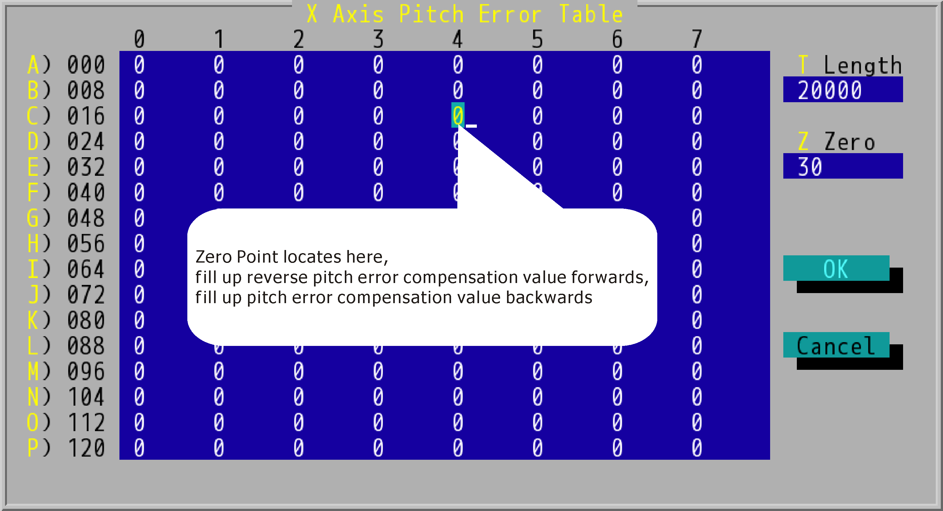
"X Axis Pitch Error Table" Zero Setting Diagram