5.1.2 Introduction of 5-axis Machining
In a general three-axis milling machine, the tool is held by the spindle and is parallel to the Z-axis direction. The tool rotates to mill the workpiece with only one fixed direction (as shown in the figure below).
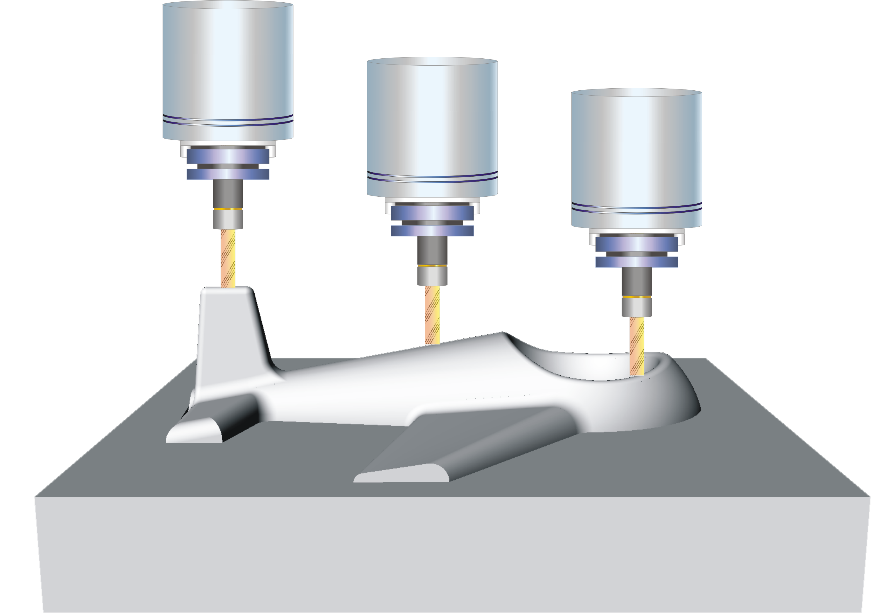
3-axis Machining
The difference in five-axis machining is that the machine table is additionally provided with two rotating mechanisms so that the tool can cut the workpiece at different angles (as shown in the figure below).
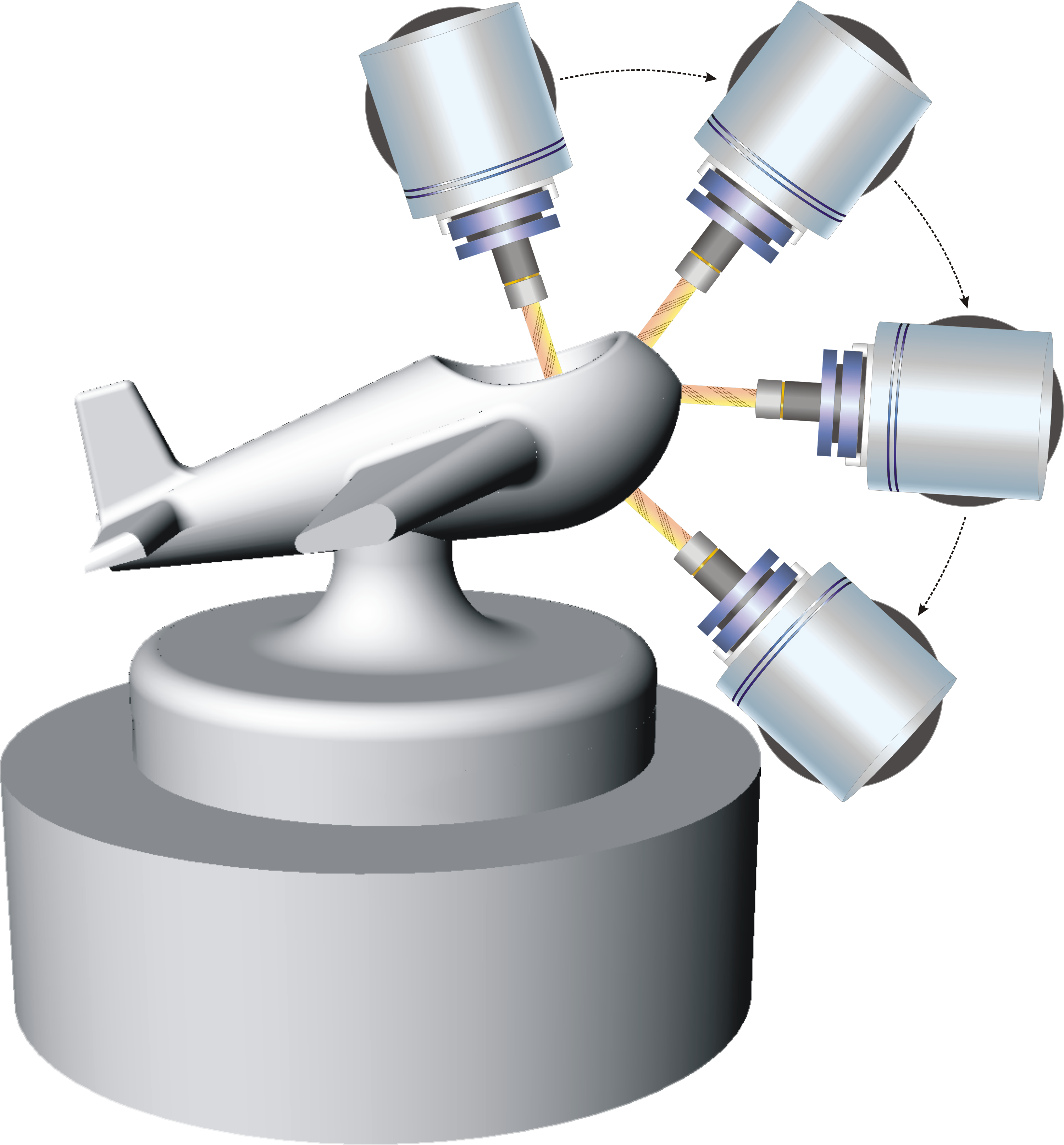
5-axis Machining
These two additional rotary mechanisms are controlled by the CNC to the axes of the two rotary axes, usually the B and C axes or the A and C axes.
So a typical three-axis program is written as follows:
G01 X_ Y_ Z_ F_; X_ Y_ Z_ is the tool tip point.
The five axis program is written as follows:
G01 X_ Y_ Z_ B_ C_ F_; X_ Y_ Z_ is the tool tip point, B_ C_ is the tool direction, F_ is the tool nose point speed.