3.2.5.3.1 Line Drill Pattern
Format: G70.07 G_X_Y_Z_R_I_J_L_Q_P_F
"Line Drill Pattern" command makes drilling holes aligned.
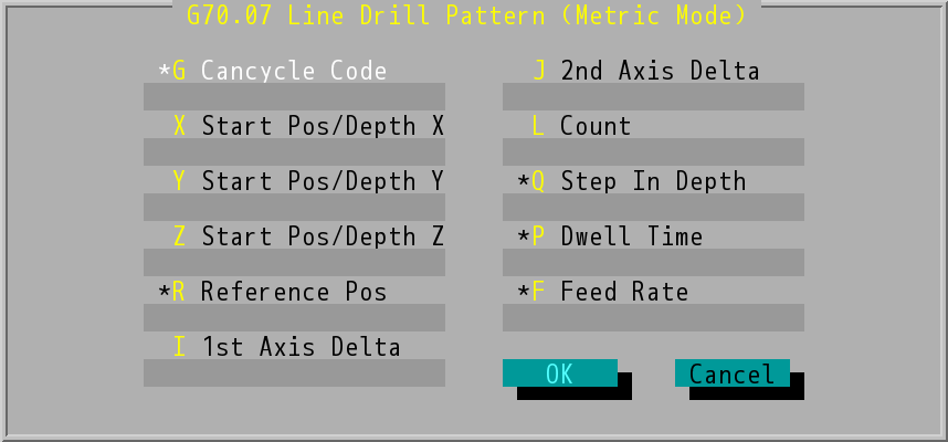
"G70.07 Line Drill Pattern (Metric Mode)" Dialog Box
Line Drill Pattern
- Cancycle Code (G value): Users type in the optional data field based on the selected Cancycle Code (G73~G89).
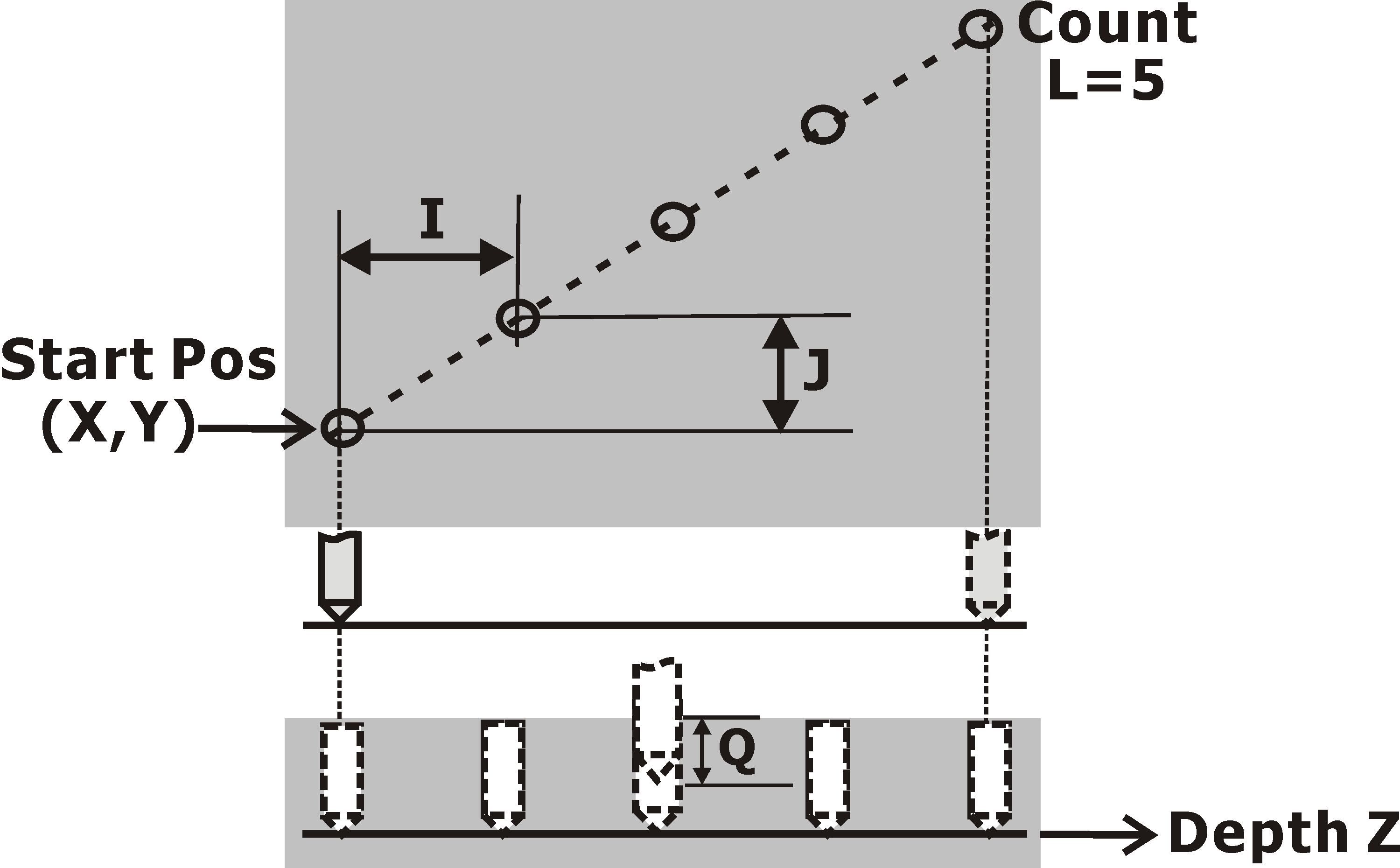
- Start Pos/Depth (X/Y/Z): start position and depth. G90/G91 (absolute positions/incremental values) and G98/G99 (start position return/reference position return) commands can be adopted.
- Refrence Pos (R value): reference position for machining.
- 1st Axis Delta (I value): distance between two holes on 1st axis.
- 2nd Axis Delta (J value): distance between two holes on 2nd axis.
- Count (L value): number of holes, it should be positive.
- Step In Depth (Q value): the depth being machined per layer. U_/V_/W_ will automatically determine whether it is U_, V_ or W_ depending on the selected plane mode (G17/G18/G19).
- Dwell Time (P value): spindle dwell time after reaching the bottom of drilled hole.
- Feed Rate (F value): the velocity at which the cutter is fed, the system will adopt the value set last time if users do not make any changes.
- When "Line Drill Pattern" command is finished, the tool will retract perpendicular to start position of the last hole.
Note: |
Start height refers to the depth of the 3rd-axis on the selected plane (G17/G18/G19). |