![]() 3.5.17.2 Tool Compensation
3.5.17.2 Tool Compensation
The user can set the number of pre-check blocks according to the processing requirements to define the maximum number of blocks to be used when performing the over-cutting test. If the number of available blocks is less than this number, the over-cutting test is performed based on the maximum number of blocks that can be provided, but at least three blocks are required to execute the over-cutting test. The maximum value of this value can be set to 10. If set to 0, no overcut detection is performed.
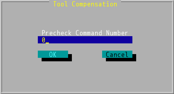
"Tool Compensation" Dialog Box
Overcut detection instructions
In the tool radius compensation mode, under certain conditions, overcut may occur when the tool radius corresponds to too large a command path. A specific overcut will be analyzed here, replacing the original path with the calculated possible path to avoid over-damaging the workpiece.
The precondition for performing the overcut test is that there are at least three motion commands. If this condition can not be met, the over-cutting test can not be performed and the over-cutting phenomenon still occurs.
1. Overcut detection reference vector
This is the vector used to analyze the overcut detection, for convenience, is termed the overcut detection reference vector.
(In the following illustration, the solid line represents the program path and the dotted line represents the knife path)
(1) Outer path
When compensation is outer path, the overcut detects will refer to vector V as below figure.
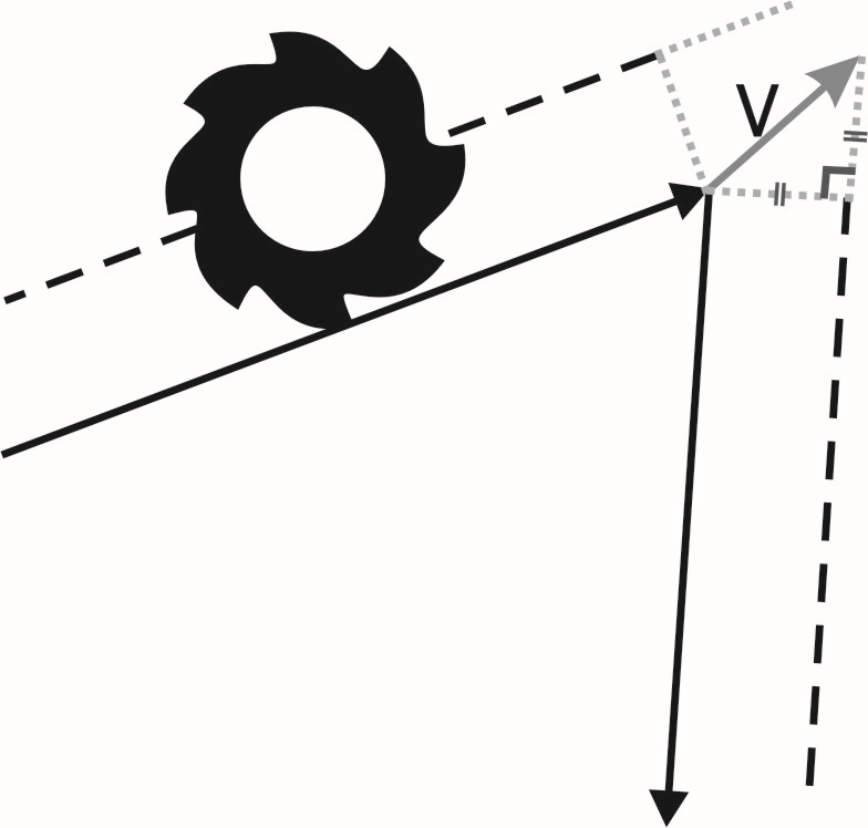
Outer Compensation Path
(2) Inner path
When compensation is inner path, the overcut detects will refer to vector V as below figure.
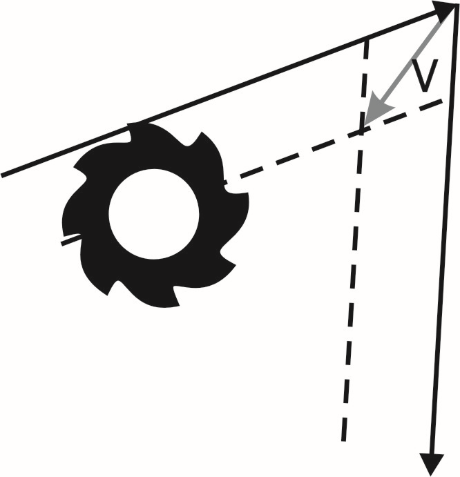
Inner Compensation Path
2. Overcut Phenomenon
About overcut discussion will discuss. Overcut has cave sharp phenomenon and pocket sharp phenomenon, and below section is going to discuss these two sharps.
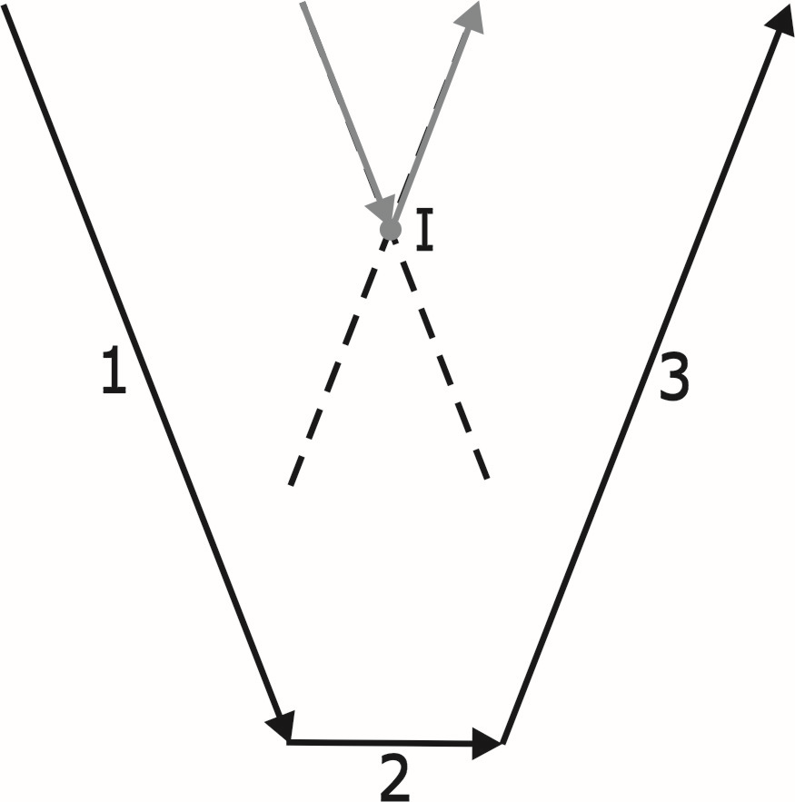
(1) Cave sharp
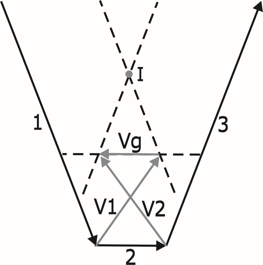
Cave Overcut
1. |
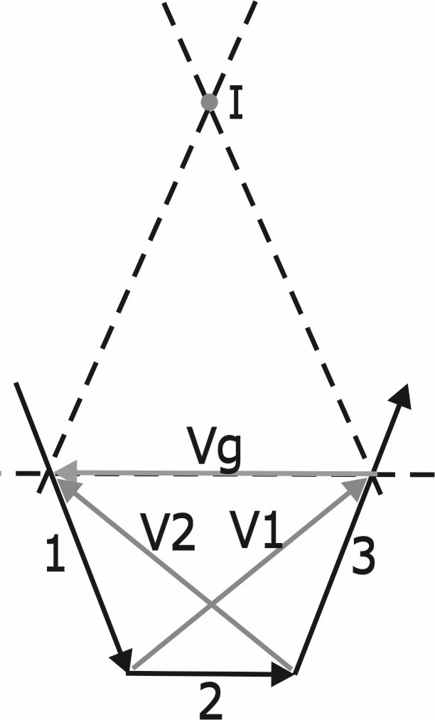
In the above figure, V1 is the overcut detection reference vector calculated by the single section 1 and the single section 2, and V2 is the overcut detection reference vector calculated by the single section 2 and the single section 3. |
2. |
Connect V1 to V2 to become a vector Vg, compare Vg with a vector formed by a single block 2, and if the angle difference is greater than or equal to 90 degrees and less than or equal to 270 degrees, it is judged as over-cutting phenomenon. |
3. |
If overcut occurs, then the tool radius compensation will ignore the single block 2, and the single block 1 and the single block 3 will do the calculation of the normal tool radius compensation. Therefore, after the compensation of the single block 1, the path will only go to point I, Block 2 will be ignored and the path to block 3 will be shown directly (as shown below). |
Block 2 Will be Bypassed If Overcut Occurs
If the tool diameter is large, the angle difference between the direction from the start point of single block 1 to the point I and the vector formed by single block 1 is greater than or equal to 90 degrees or less than 270 degrees (as shown in the following figure), then it is judged as a dangerous phenomenon. An error message will still be displayed and the program execution will be stopped, even if "Error message for tool compensation overcut" is not selected in the "F2→Parameter→Attribute" dialog box.
Tangential Overcut Dangerous Phenomenon
(2) Pocket Overcut
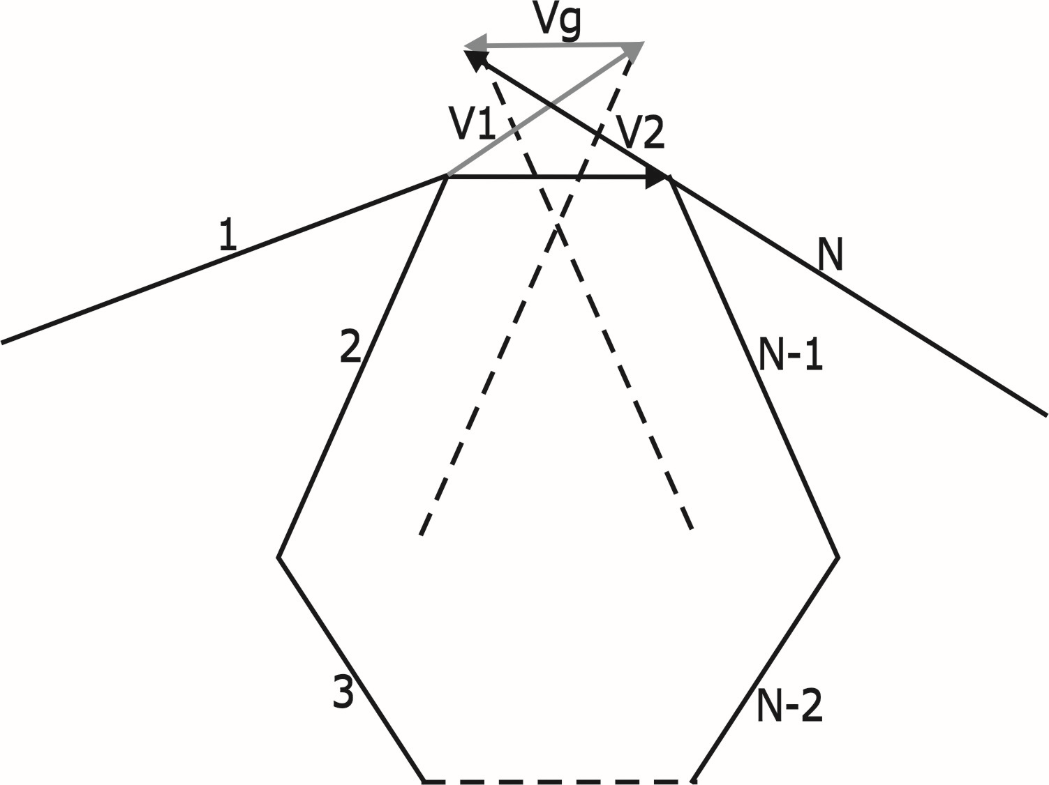
Pocket Overcut
Suppose that N is the number of command blocks to execute overcut check.
1. |
Calculate block 1 and 2 to get the overcut check reference vector V1. |
2. |
Calculate block N-1 and N to get the overcut check reference vector V2. |
3. |
Connect V1 and V2 to form vector Vg. |
4. |
The vector formed from block 1 end position to block N start position is called gap vector. |
5. |
Compare Vg and gap vector, if the angle difference is greater than/equal to 90 degrees or less than/equal to 270 degrees, it will be seen as overcut. If overcut does not occur, it will move to the next step. If overcut occurs, it will go to step 10. |
6. |
Repeat step 2~5 on block N-2 and N-1. |
7. |
Repeat step 2~5 on block N-3 and N-2. |
8. |
………………. |
9. |
Repeat step 2~5 on block 3 and 4. If overcut does not occur, it will execute block 1 according to normal tool radius compensation. If overcut occurs, it will go to the next step. |
10. |
Suppose that the overcut blocks are N-1 and N, the system will do calculation and overcut check on block 1, gap vector, and block N. |
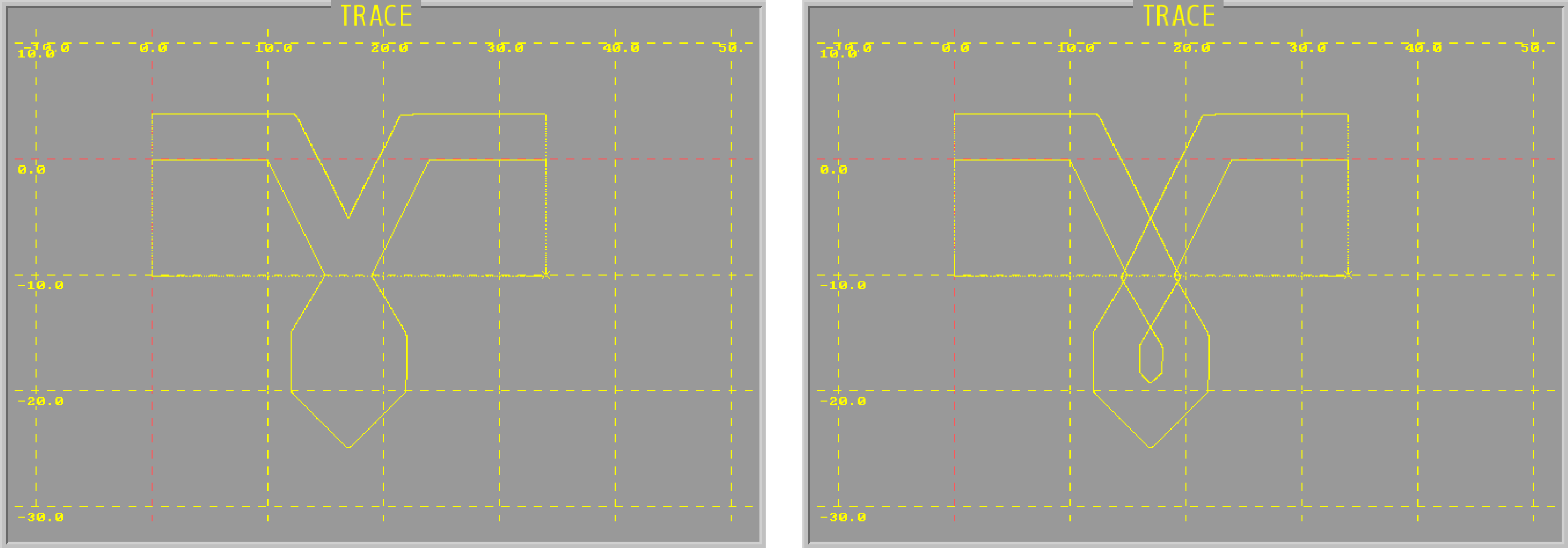
The following is the example of the compensation of the cutting path on whether the overcut check is excecuted.
Example 1
Program:
G00 XY
D1
M97 P0001
G00 XY
D2
M97 P0001
M30
O0001
G41
G00 X10. Y10.
G01 X15. F1000
X17. Y0.
M08
M09
X18.
X20. Y10.
X25.
G40
G00 X30. Y0.
M99
1. D2=0.3
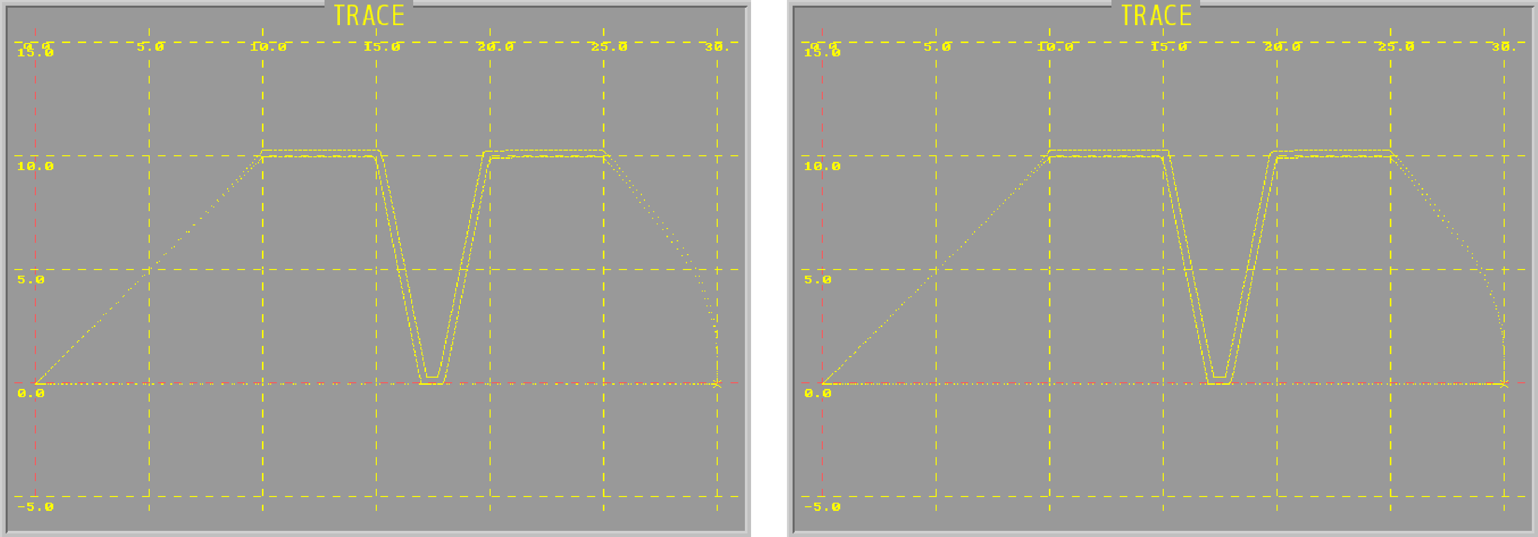
With overcut check |
Without overcut check |
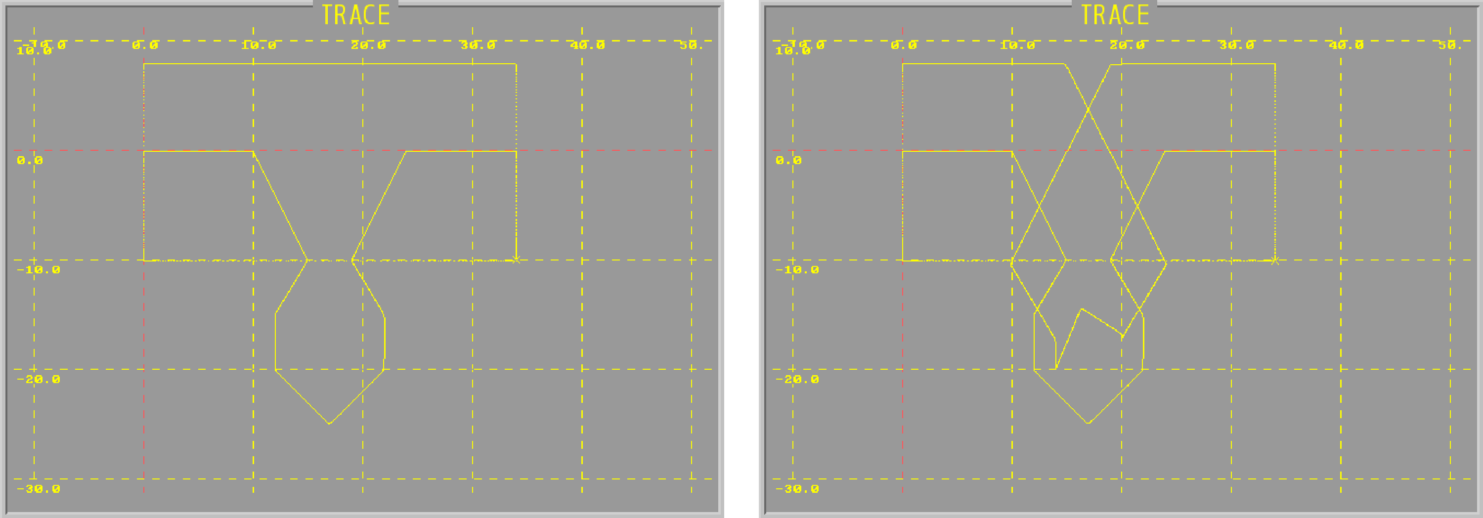
2. D2=1.5
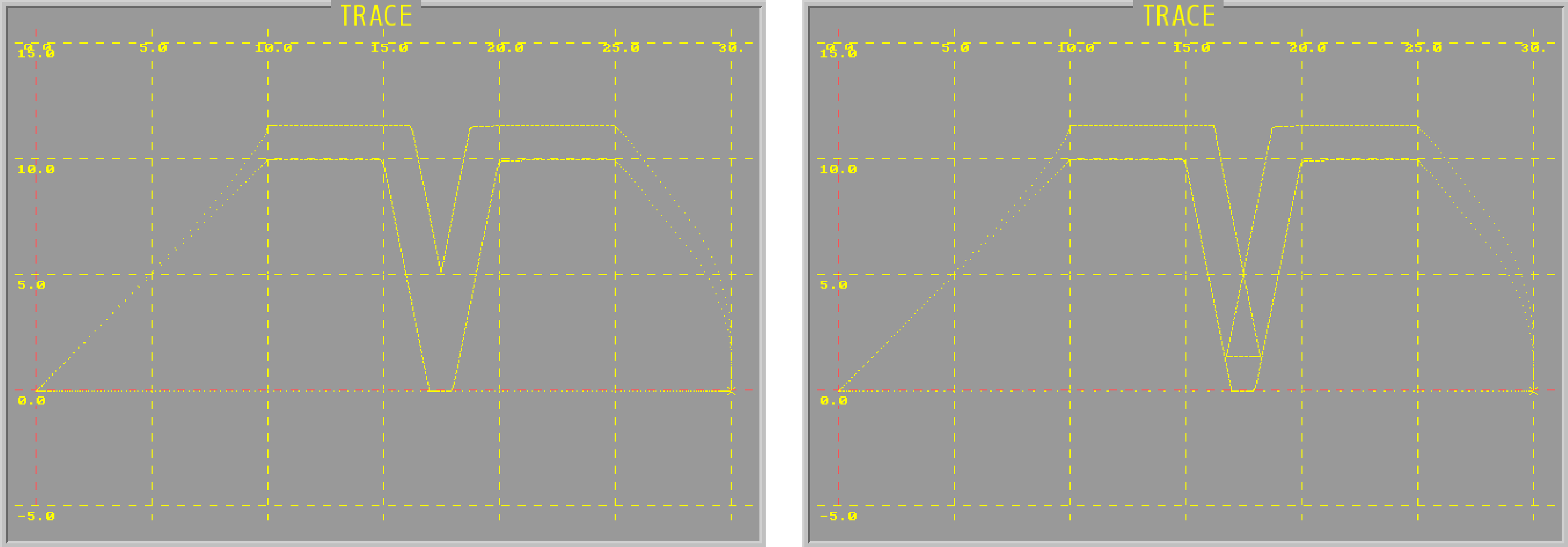
With overcut check |
Without overcut check |
3. D2=3
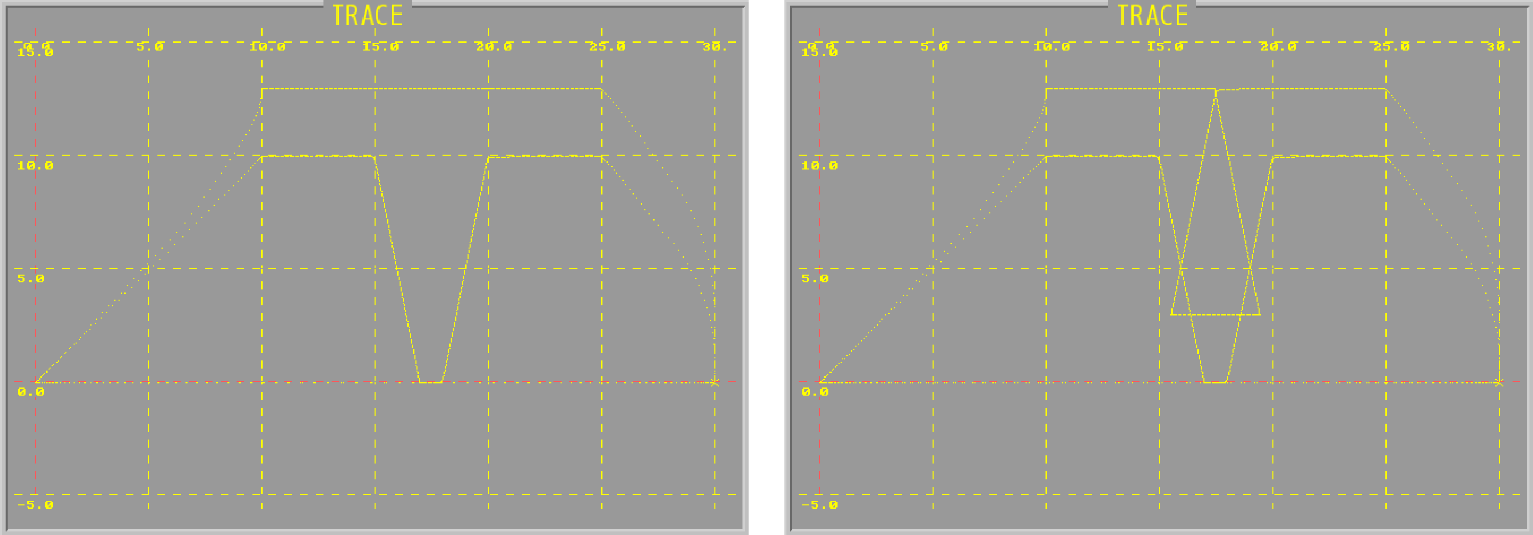
With overcut check |
Without overcut check |
Example 2
Program:
G00 XY-10.
D1
M97 P0001
G00 XY-10.
D2
M97 P0001
M30
O0001
G41
G00 Y0.
G01 X10.
X15. Y-10. F1000
X12. Y-15.
Y-20.
X17. Y-25.
X22. Y-20.
Y-15.
X19. Y-10.
X24. Y0.
X34.
G40
G00 Y-10.
M99
1. D2=1
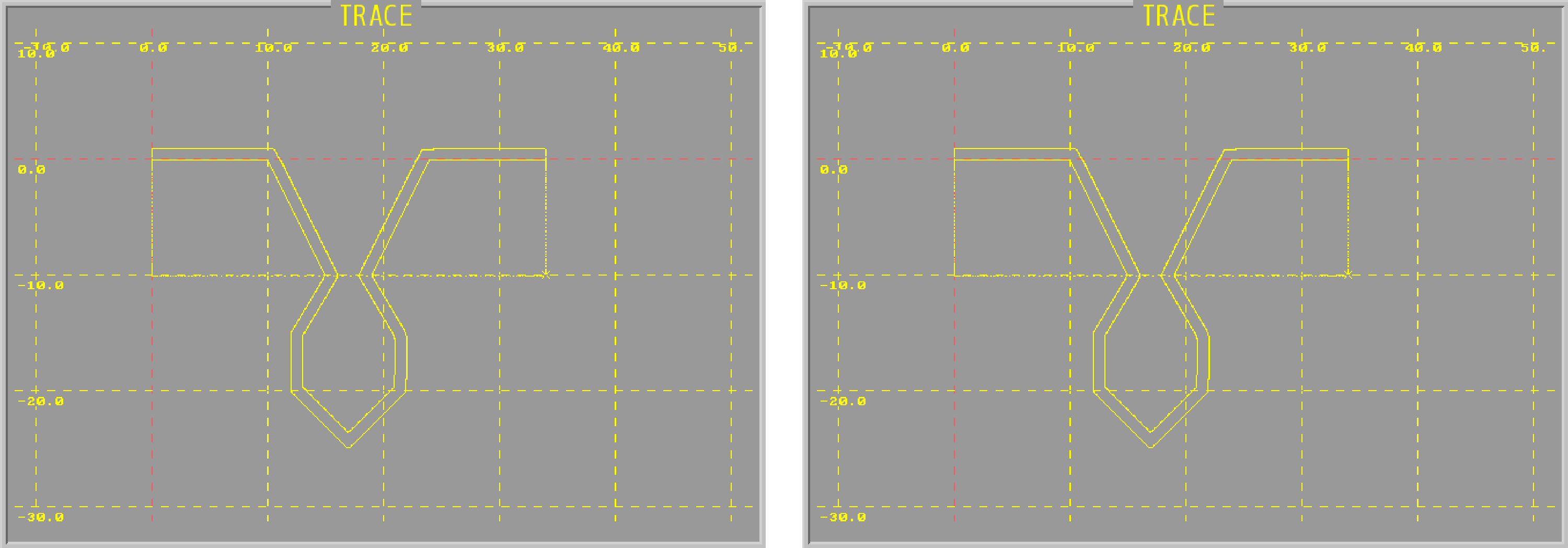
With overcut check |
Without overcut check |
2. D2=2
With overcut check |
Without overcut check |
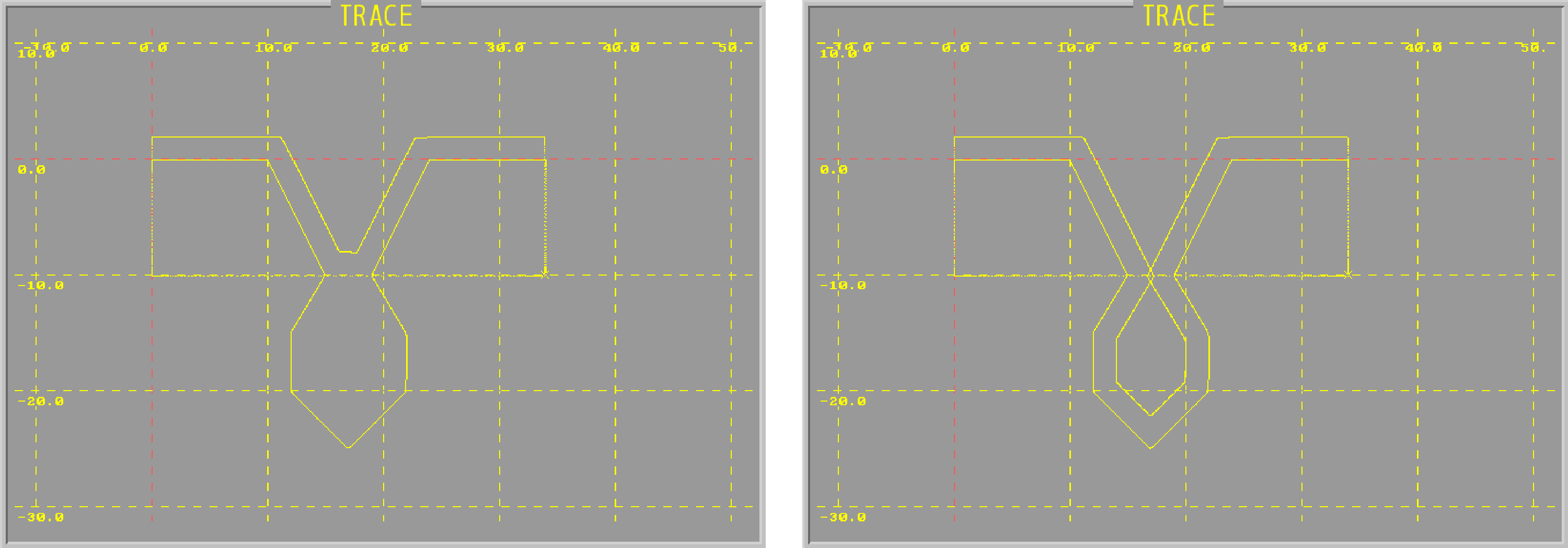
3. D2=4
With overcut check |
Without overcut check |
4. D2=8
With overcut check |
Without overcut check |