3.2.5.3.3 Arc Drill Pattern
Format: G70.09 G_X_Y_Z_R_C_A_I_L_B_Q_P_F_
"Arc Drill Pattern" command makes the drilling holes arced or circular.
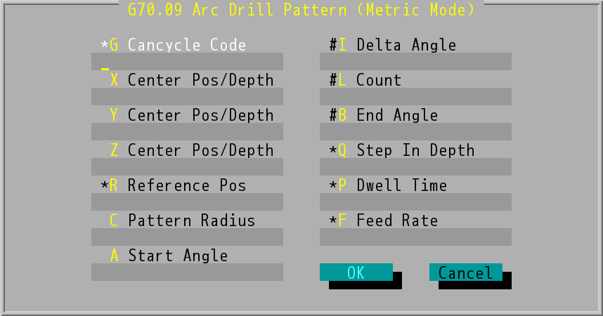
"G70.07 Arc Drill Pattern (Metric Mode)" Dialog Box
Arc Drill Pattern
- Cancycle Code (G value): Users type in the optional data field based on the selected Cancycle Code (G73~G89).
- Center Pos/Depth (X/Y/Z): center position and depth. It can be absolute positions or incremental values, which depend on G90 or G91 mode (absolute positions/incremental values).
- Refrence Pos (R value): reference position for machining.
- Absolute or incremental coordinates can be used for the center of the circle.
- Text boxes labeled with "#" can make up three different formats of "Arc Drill Pattern" command:
- Key in values in data field of Delta Angle and Count.
- Key in values in data field of End Angle and Count.
- Key in values in data field of End Angle and Delta Angle.
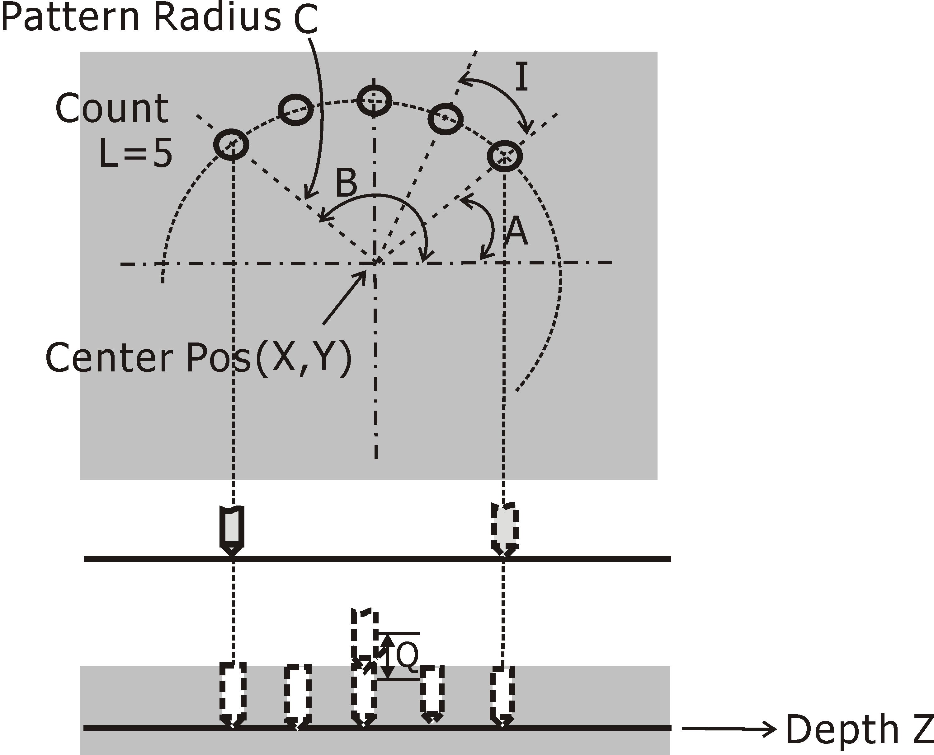
- Pattern Radius (C value): the radius of "Arc Drill Pattern", it must be positive.
- Start Angle (A value): the start angle of "Arc Drill Pattern".
- Delta Angle (I value): the angle between two drilled holes.
- Count (L value): number of holes.
- End Angle (B value) must be greater than Start Angle (A value). For example, the End Angle must be 390° (360°+30°) instead of 30°.
- If users enter all values in data field of Delta Angle, Count, and End Angle, the value of End Angle will be ignored.
- Step In Depth (Q value): the depth being machined per layer.
- Dwell Time (P value): spindle dwell time after reaching the bottom of drilled hole.
- Feed Rate (F value): the velocity at which the cutter is fed, the system will adopt the value set last time if users do not make any changes.
- When "Arc Drill Pattern" command is finished, the tool will retract perpendicular to start height of the last hole.
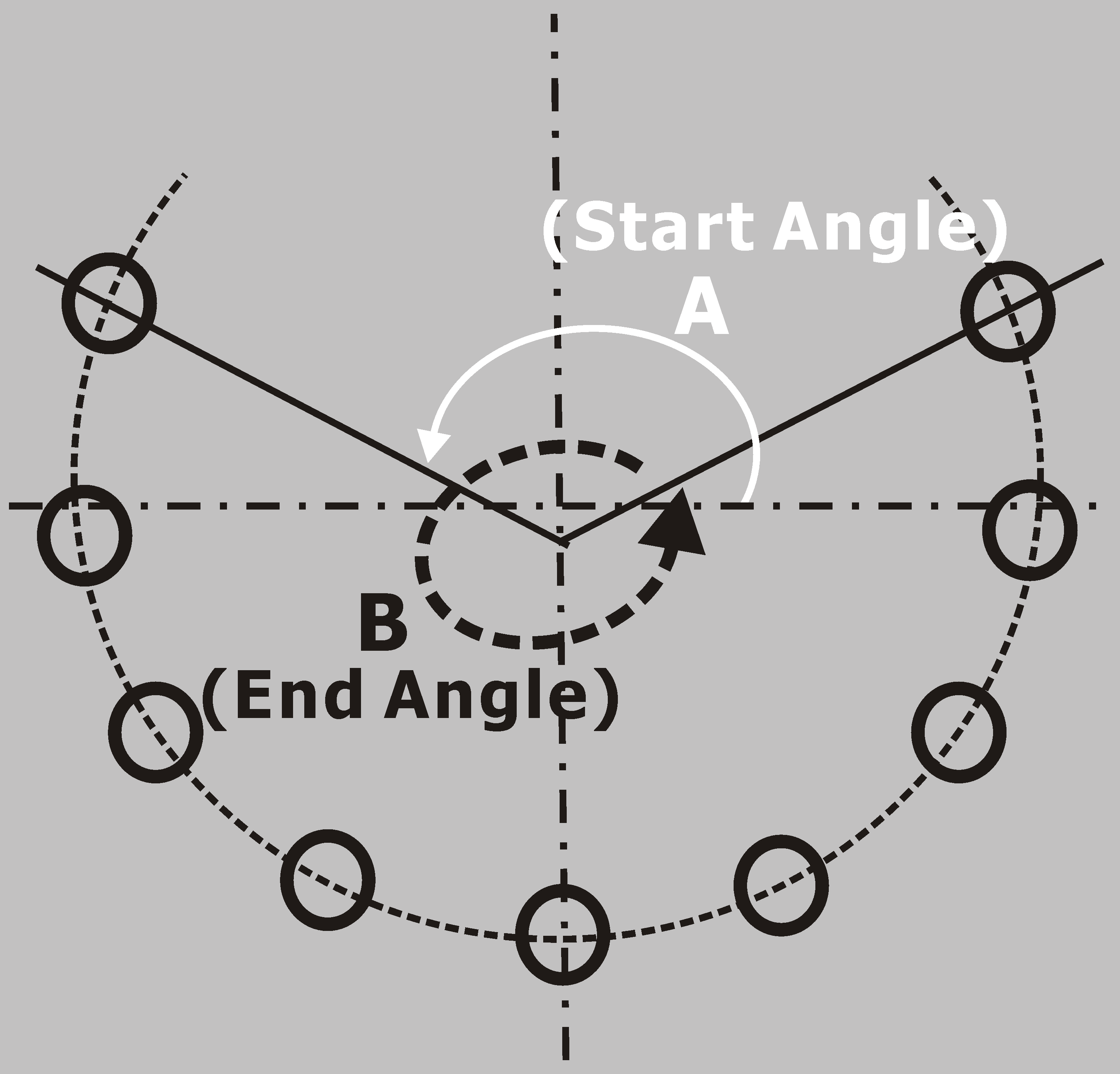
Start Angle and End Angle