3.2.5.6.2 Circular Pocket Machining
Format: G70.01(G02/G03)(P_)X_Y_Z_R_U_(C_ J_ K_)Q_I_(E_ F_)
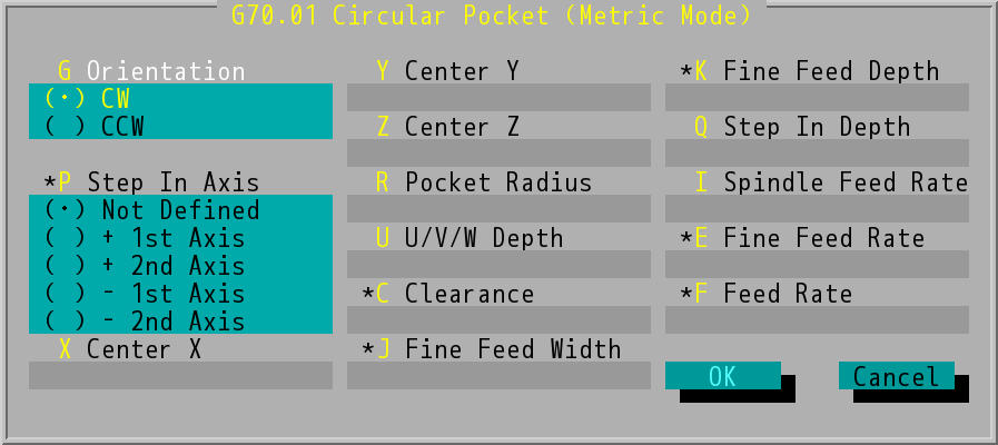
"G70.01 Circular Pocket (Metric Mode)" Dialog Box
- Orientation (G): The cutting orientation can be clockwise (CW, G02) or counterclockwise (CCW , G03).
- Step In Axis (P): can be Not Defined, + 1st Axis, + 2nd Axis, - 1st Axis, and - 2nd Axis, which will be shown as P0~P4 command in the program. The orientation of 1st axis and 2nd axis are depends on the working plane (G17/G18/G19).
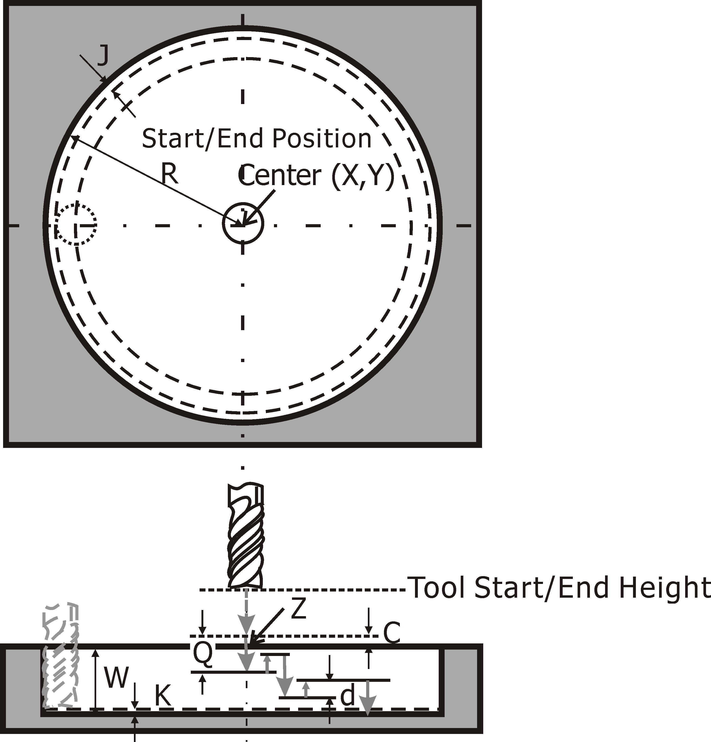
- Center X/Y/Z: center of pocket machining. It can be absolute positions or incremental values.
- Pocket Radius (R value): the radius of circular pocket being machined.
- U/V/W Depth (U value): the depth of the pocket. The value is negative.
- Clearance (C value): the safe starting height for machining.
- Fine Feed Width (J value) and Fine Feed Depth (K value): the width and depth of fine cut.
- Step In Depth (Q value): the depth being machined per layer.
- Spindle Feed Rate (I value): feed rate of spindle. Please refer to INCON-M84/M86/M86R Integration Manual for more information.
- Fine Feed Rate (E value): feed rate of fine cutting. If the value of Fine Feed Rate (E value) was left blank, system will replace the value with half of Feed Rate (F value) value.
- Feed Rate (F value): the velocity at which the cutter is fed, the system will adopt the value set last time if users do not make any changes.
- Users need to set the number of tool table (D_) and the tool radius before processing pocket machining.
Circular Pocket Machining