3.2.5.8.2 Circular Side Surfacing
Format: G70.05(G02/G03)I_(P_)X_Y_Z_ R_U_(F_)
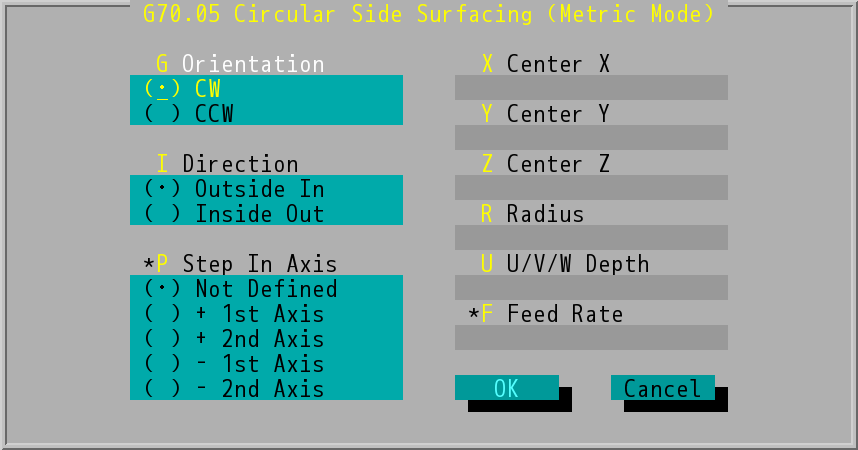
"G70.05 Circular Side Surfacing (Metric Mode)" Dialog Box
- Orientation (G): The cutting orientation can be clockwise (CW, G02) or counterclockwise (CCW , G03).
- Direction (I): Outside in or Inside out, which will be shown as I0/I1 command in the program.
- Step In Axis (P): can be Not Defined, + 1st Axis, + 2nd Axis, - 1st Axis, and - 2nd Axis, which will be shown as P0~P4 command in the program. The orientation of 1st axis and 2nd axis are depends on the working plane (G17/G18/G19).
- Center X/Y/Z: center of circular side surfacing. It can be absolute positions or incremental values.
- Radius (R value): the radius of the circular side surfacing circle.
- U/V/W Depth (U value) defines the depth of the side surfacing circular.
- Feed Rate (F value): the velocity at which the cutter is fed, the system will adopt the value set last time if users do not make any changes.
- Users need to set the number of tool table (D_) and the tool radius before processing side surfacing machining.
- The outside-in side surfacing and inside-out side surfacing of the circular share this dialog box, in the side surfacing machining direction, I0 and I1 will be used to indicate outside-in side surfacing or inside-out side surfacing.
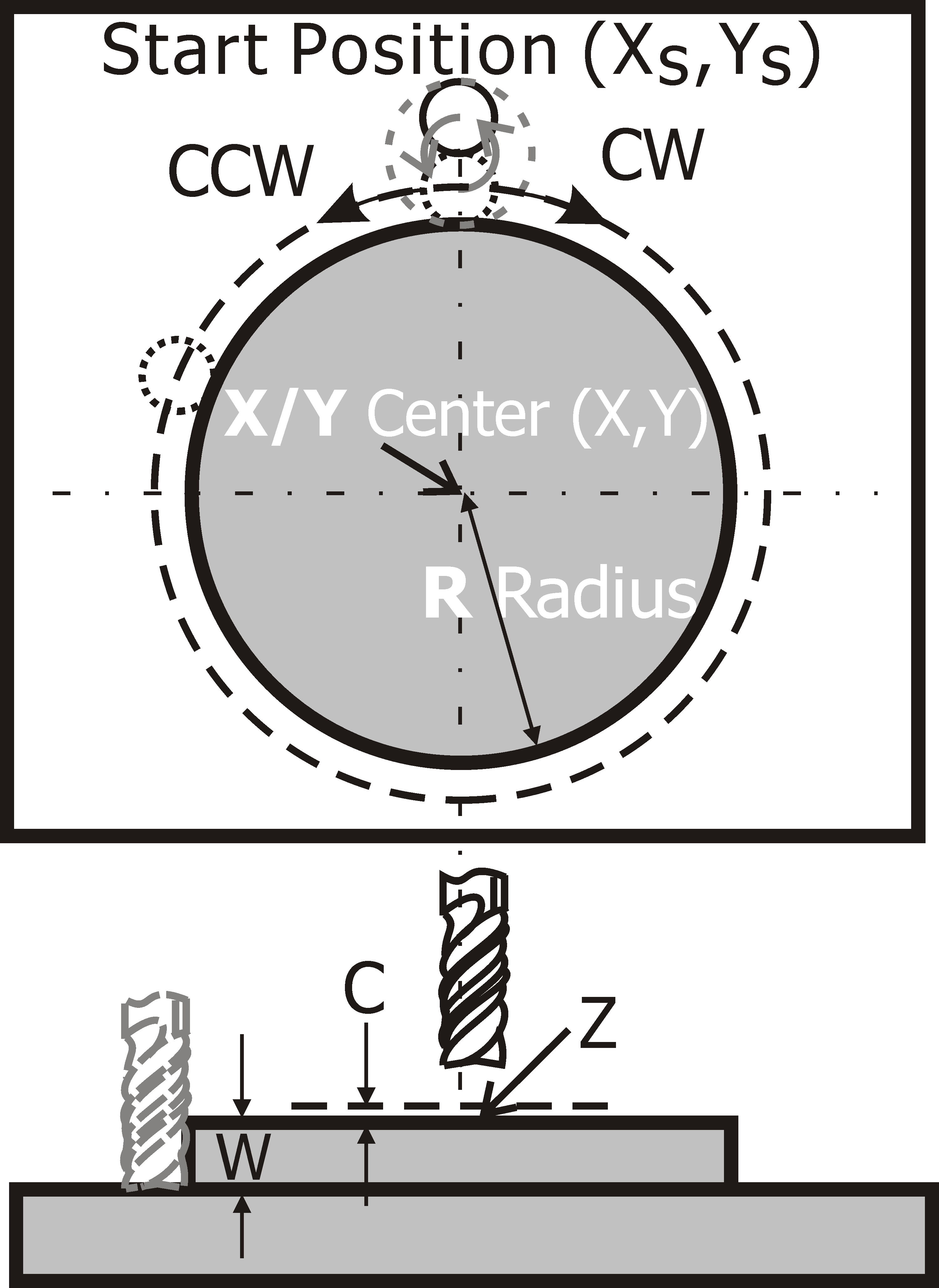
Circular Side Surfacing (Outside in)
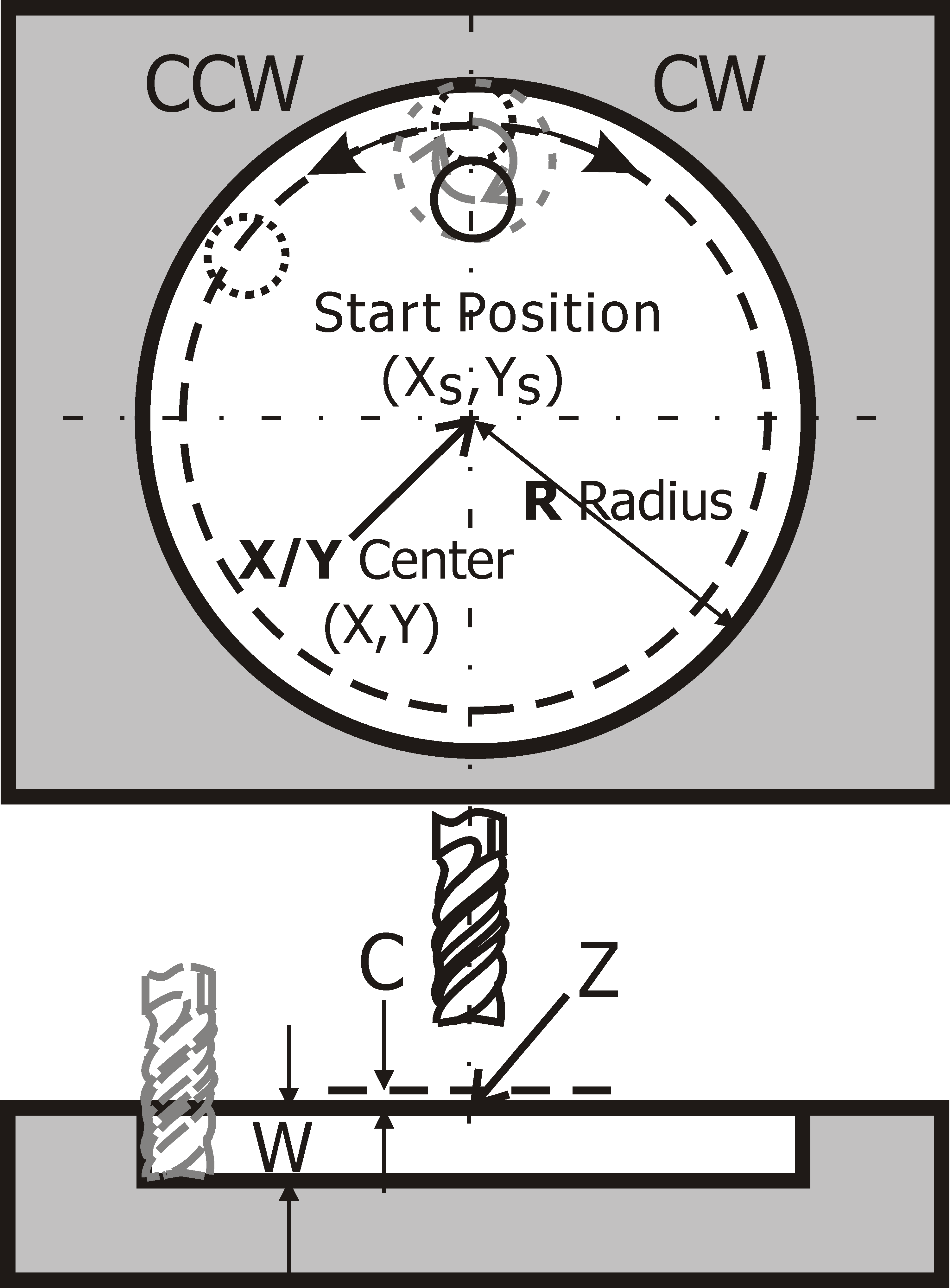
Circular Side Surfacing (Inside out)