3.2.5.1.3 Circular Interpolation (G02/G03)
Format:
G02/G03 X_Y_ (Z_)R_F_ |
; Radius format |
G02/G03 X_Y_ (Z_)I_J_ (I_K_/J_K_)F_ |
; Center format |
G02/G03 I_J_ (I_K_/J_K_)A_F_ |
; Angle format |
From the "Command Insertion Aid" menu, select "Circular Interpolation", there will be a dialog box (as shown in the figure).
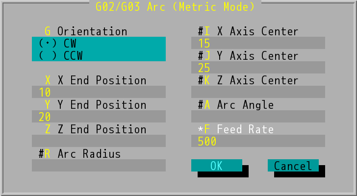
"G02/G03 Arc (Metric Mode)" Dialog Box
Key in values in each of the data field and press ENTER, there will be a corresponding block added in program window (as shown in the figure). This dialog box can be inserted into the G02/G03 positive or negative circular interpolation command, the end of the circle or arc can be represented by absolute coordinates/incremental values or right angle/polar coordinates.
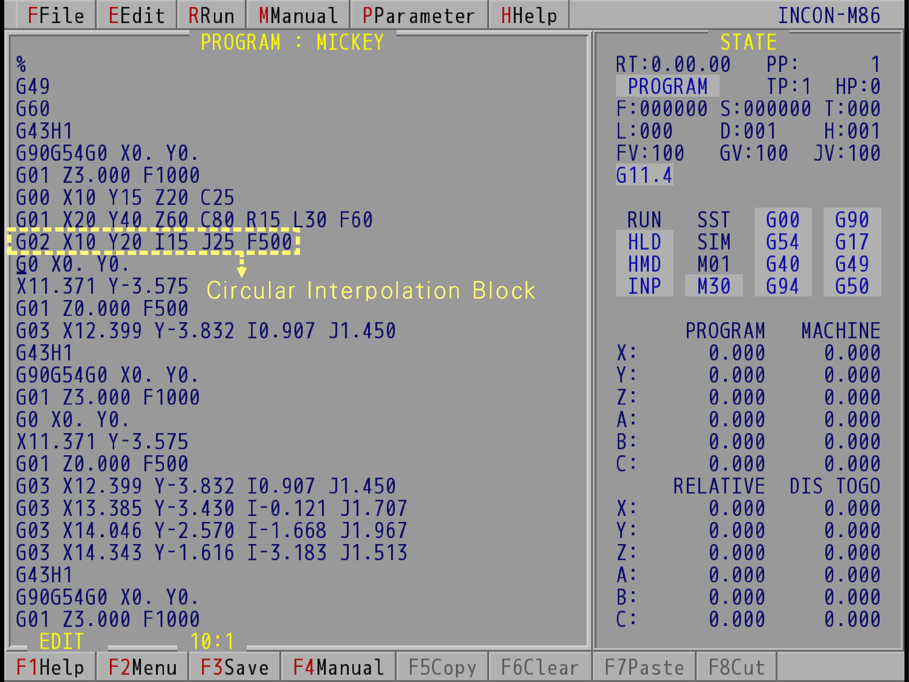
G02/G03 Circular Interpolation Block (Take INCON-M86 for example)
- Orientation (G): The cutting orientation can be clockwise (CW, G02) or counterclockwise (CCW , G03).
- X/Y/Z End Position: The end position of circular interpolation. It can be shown in absolute positions or incremental values.
- Text boxes labeled with "#" can make up three different formats of arc commands, the examples (with G17 X-Y plane) are given below:
- Radius format: Key in values in data fields of X End Position, Y End Position, and Arc Radius. If R value is negative, the arc angle will be grater than 180º.
- Center format: Key in values in data fields of X End Position, Y End Position, X Axis Center, and Y Axis Center. X Axis Center and Y Axis Center are relative distances between the center position of circle and start position.
- Angle format: Key in values in data fields of X Axis Center, Y Axis Center, and Arc Angle.
- Feed Rate (F value): the velocity at which the cutter is fed, the system will adopt the value set last time if users do not make any changes.
Note: |
For further information about G02/G03 command, please refer to Programming Codes. |