3.2.5.4.2 Grid Object Pattern
Format: G70.22 C_I_ J_A_B_(D_)
@ G70.11(G41/G42)P_X_Y_Z_(U_V_W_)C_J_K_Q_R_I_E_F_
(Contour Pocket Side Surfacing Machining is taken for example here)
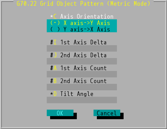
"G70.22 Grid Object Pattern (Metric Mode)" Dialog Box
Grid Object Pattern
- Axis Orientation (C value): options of the axial machining order, the command in program will be C0/C1. The axial machining order of C0 command is from X-axis to Y-axis. The axial machining order of C1 command is from Y-axis to X-axis.
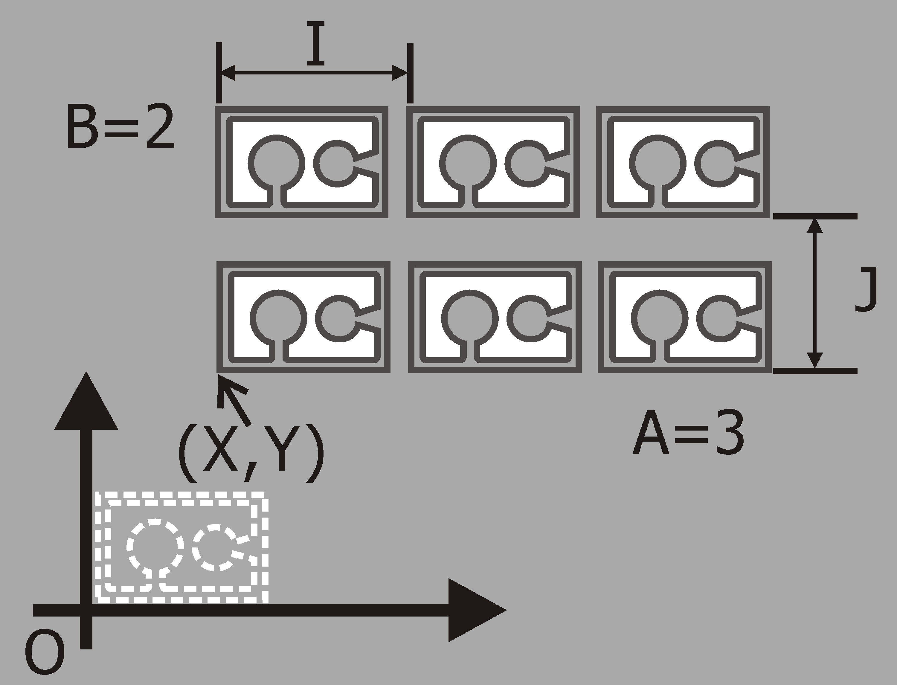
- 1st Axis Delta (I value): distance between two objects on 1st Axis.
- 2nd Axis Delta (J value): distance between two objects on 2nd Axis.
- 1st Axis Count (A value): number of objects being machined on 1st axis, it should be positive.
- 2nd Axis Count (B value): number of objects being machined on 2nd axis, it should be positive.
- The orientation of 1st axis and 2nd axis are depends on the working plane (G17/G18/G19).
- The start position (X,Y) of the first object is defined in the selected machining command following @.
- When "Grid Object Pattern" command is finished, the tool will retract perpendicular to the start height of last object.
- Tilt Angle (D value): the tilt angle of object arrangement from the start position (X,Y), which is optional. This option has "*", which means it can be worked or not, so you don't key in data, if no title angle.
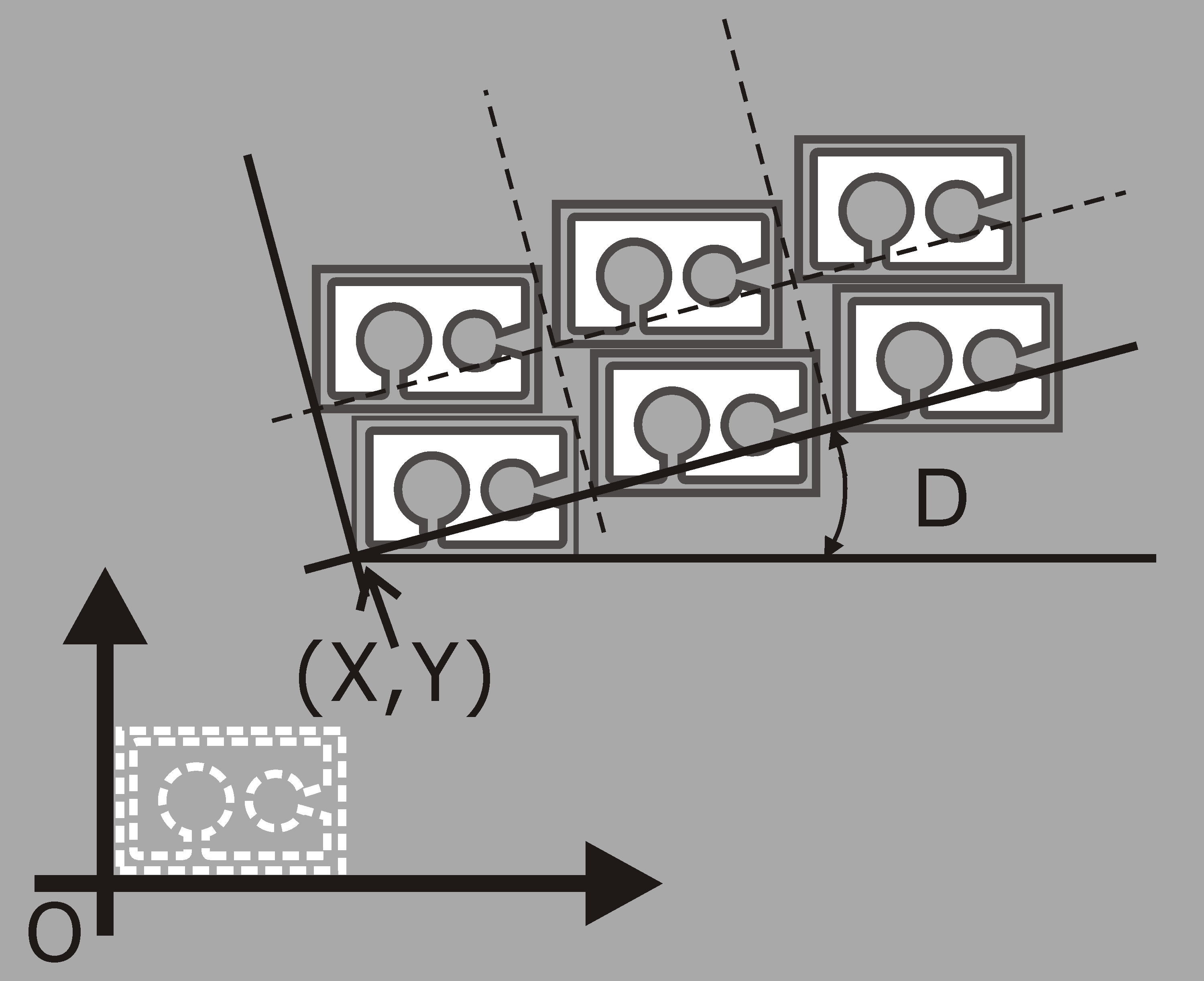
Tilt Angle of Grid Object Pattern